Welding Electrode Manufacturing
Welding Electrode Manufacturing is a complex process that should be divided into different steps: Wire Drawing and Cutting, Powder Mixing, Coat Covering, Baking. it is also important to know the details about the Pre-In-After Quality Control Process. By considering these steps, WESPEC systematically describes the production process from the beginning to the end. also, you can find the list of welding electrodes that can be produced by you with WESPEC.
1-Wire
2-Powder
3-Binder
1-Chemical Analysis
2-Grain Size Test
3-Physico-Chemical Tests
4-Mechanical Tests
1- Drawing, Straightening and Cutting
2- Dry & Wet-mixing
3-Extruder
4-Baking
5-Packing
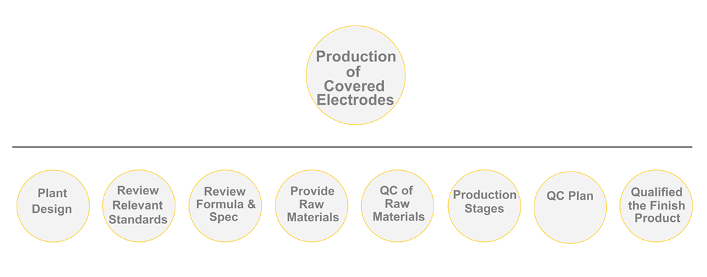
1) Plant Design for Welding Electrode Manufacturing:
WESPEC can design a welding electrode manufacturing plant based on your requirements. This plan will include a detailed calculation of all your requirements for the production of the best quality product. The main topics are as below:
1-Factory design and construction (land and buildings)
2- Power requirements (electrical, gas, water)
3-Determine the machine needed and design of plant lay out.
4- Specify laboratory equipment required or outsourcing.
5-Specify the equipment needed to carry.
6-Man power requirement.
7-Working Capital Management for welding electrode production factory.
Note: If You already have a Welding Electrode Factory, WESPEC can help you Produce a Quality Product Depending on Your Capabilities.
2) Review Relevant Production Standards:
It is necessary to find out what are the standards for determining the quality of a welding electrode. This is because we guarantee the final quality of the product and its compliance with relevant standards.Also By knowing the standard code of the product you intend to produce, the WESPEC will provide an accurate estimate of the raw materials required, the production process, and how to test the final product.
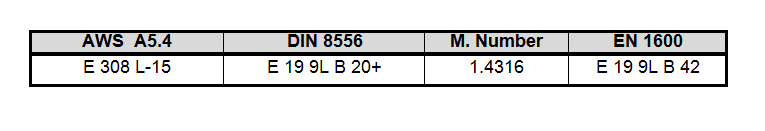
For instance E308L-15 has these relevant standards as follows:
Welding Electrode Standard Code
3) Review Relevant Formulation & Specification of Welding Electrode:
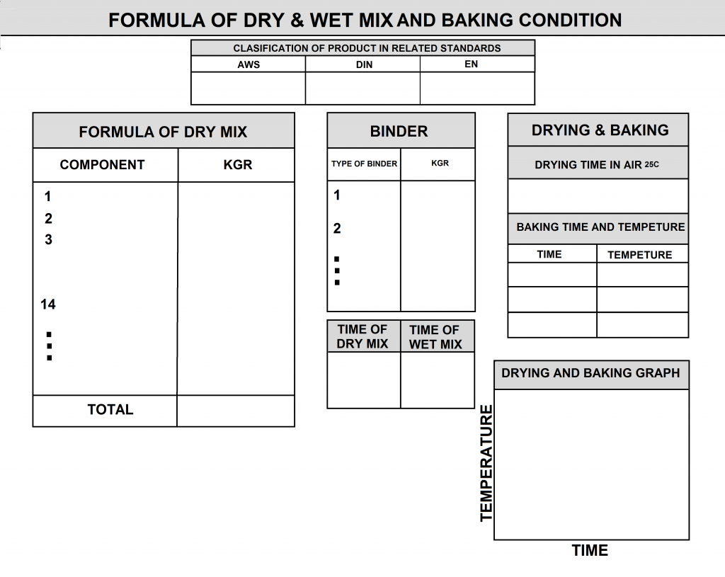
The Technical Documents used by WESPEC to produce high-quality welding electrodes are as follows:
- Formula of Dry and Wet Mix: The exact weight of each coating component in the formula, as well as the precise amount of binder.
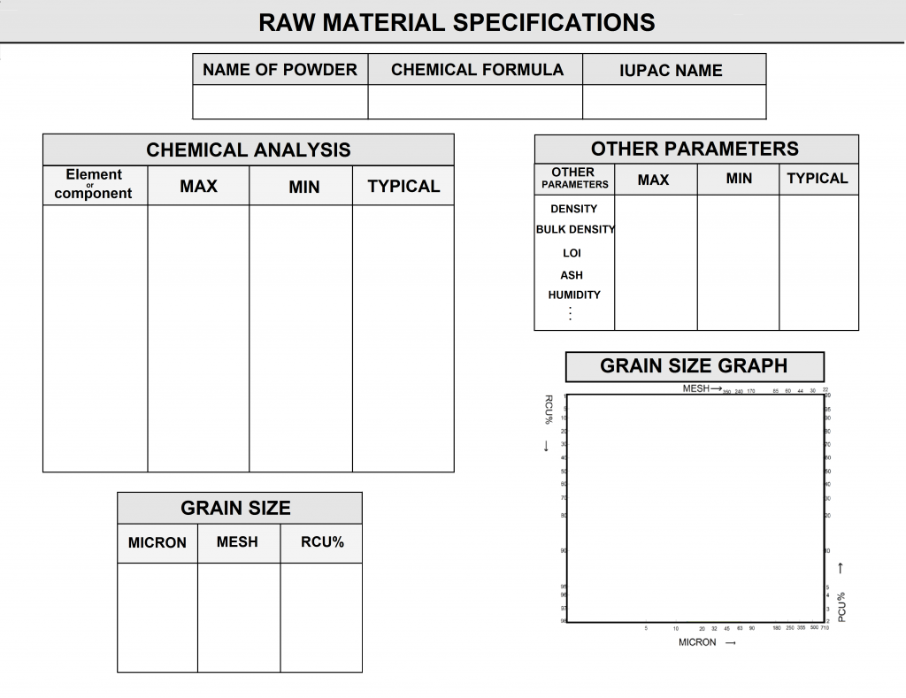
- Specification of Raw Materials (Powders, Binders, Wire): Detailed technical specifications of each raw material.
- For powdered materials: chemical analysis, particle size analysis, and other specifications such as density, LOI, etc.
- For core wire: specifications include chemical analysis and mechanical properties such as tensile strength, yield strength, and elongation, as well as permissible geometric dimensions.
- For binders: detailed information including chemical analysis of silicate compounds and technical details such as viscosity, Baume, molar ratio, weight ratio, etc.
- Production Instructions: Comprehensive technical information for the production of welding electrodes, including wet and dry mixing times, wet dough specifications, press pressure, electrode geometric dimensions, drying and baking temperatures and times, etc.
WESPEC Customers Receive a Document Entitled “WELDING ELECTRODE PRODUCTION KNOW-HOW”.(Click Here)
Welding Electrode Manufacturing Formula
3-1) Wire : The exact specifications of the wire include the chemical analysis, with the maximum, minimum, and typical values of each element shown in the specification sheet. The mechanical properties of the coiled wire, with a diameter of 5.5 mm or 6.5 mm, are also mentioned in this specification sheet.
Coiled Wire for Manufacturing of Welding Electrode
Specification of the Wire

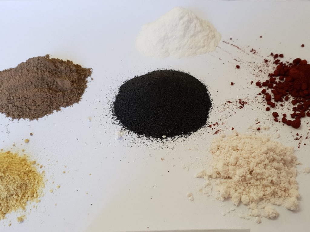
3-2) Powder: Each welding electrode can contain, on average, 10 to 20 types of minerals, chemicals, metals, and ferroalloys. The specification sheet for each powder includes detailed properties such as chemical analysis, sieve analysis, density, and humidity, as shown in the figure.
Sample of Raw Materials for Production of Covered Electrodes
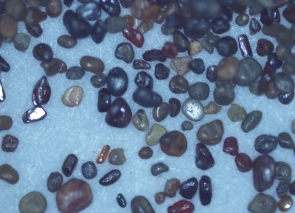
Microscopic Image of Rutile Sand
Specification of the Powder
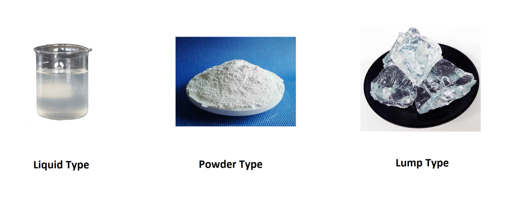
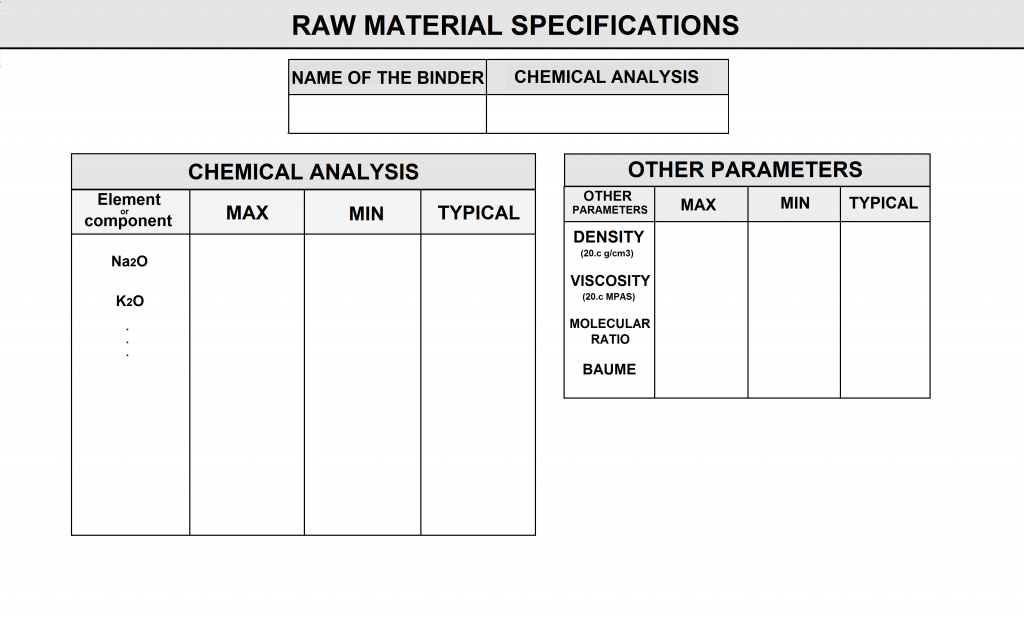
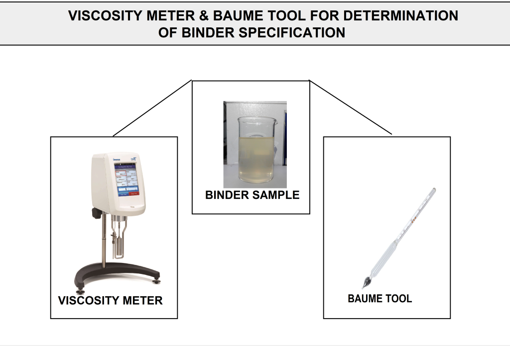
3-3) Binder: The main task of the binder is to adhere the required powder coating to the wire surface of the welding electrode. This group of materials primarily consists of sodium and potassium silicate compounds. The specification sheet for these raw materials includes precise properties such as chemical analysis, density, viscosity, molar ratio, and Baume, as shown in the figure.
Depending on the situation, this raw material is supplied in three forms: liquid, lump, and powder. In its liquid state, the adhesive is ready for use in the production process, whereas in the lump and powder states, it requires processing before use.
Types of Binder for Production of Covered Electrodes
Specification of the Binder
4) Prepare of Raw Material based on spec
WESPEC knows the qualified raw material suppliers for Welding Electrode Manufacturing from around the world. We can help you in purchasing raw materials based on Described Know-How.
5) Qc of Raw Materials for Welding Electrode Manufacturing
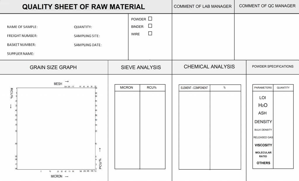
It is necessary to test materials before welding electrode manufacturing. All the materials need to be tested and each item of results should compare with its specification range. each number inserted in this sheet will compare with the related specification.
Final QC sheet of Raw Materials
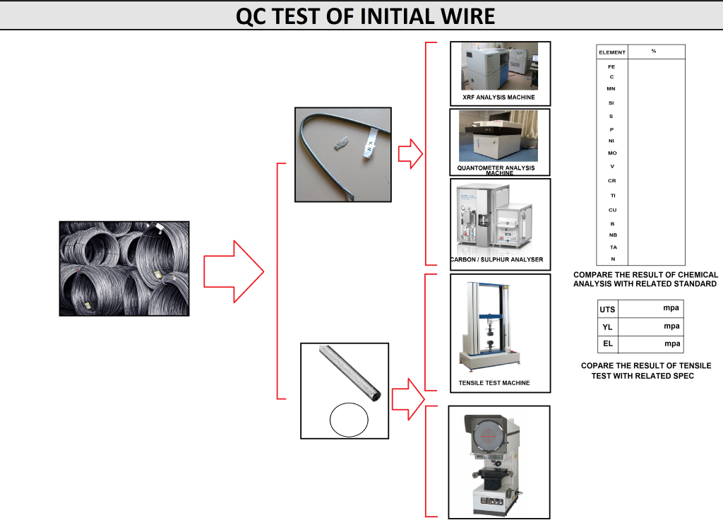
As shown in the image below, a variety of machines are required for testing the quality of raw materials. Each of these machines comes with its own instructions for testing raw materials. Of course, all these tests are necessary when 120 types of electrodes are targeted for production. You can either purchase some of these testing machines and use them within the manufacturing plant or reduce costs by outsourcing the material testing process to approved laboratories.
Required Tests for Raw Materials of Welding Consumables
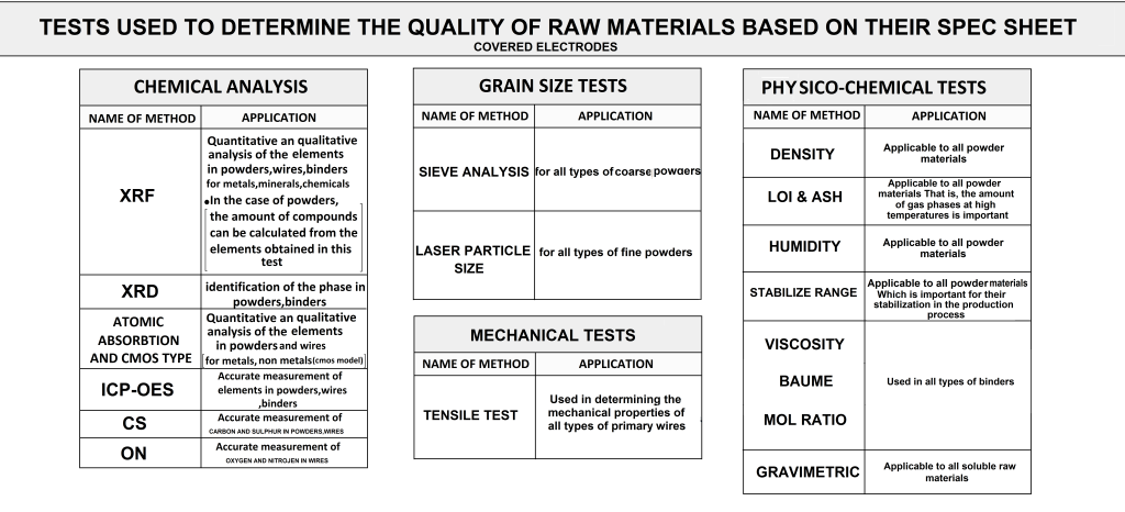
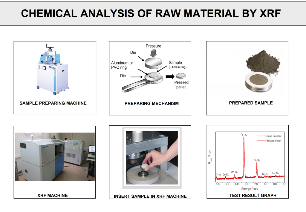
5-1) Chemical Analysis:
Different methods are available to determine the quantitative and qualitative analysis of the elements and compounds present in the raw materials:
•XRF
•XRD
•Atomic Absorption
•Carbon/Sulphur
•Oxygen/Nitrogen
•ICP
Required Tests for Raw Materials of Welding Consumables
Required Tests for Raw Materials of Welding Consumables
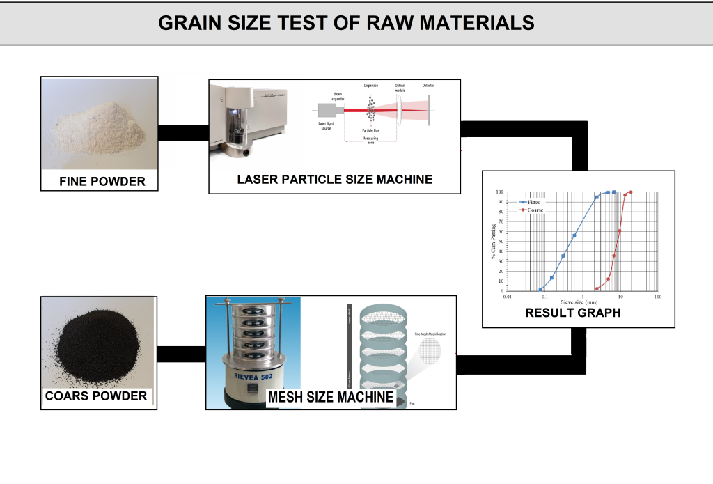
5-2) Grain Size Test (Sieve Analysis):
After the acceptance of chemical properties, another critical parameter that significantly affects the quality of the powder is grain size. Different methods are available to control grain size. For coarse powders, sieve analysis is used, while for fine powders, the laser particle size method is more common. The results are evaluated using the grain size graph.
Required Tests for Raw Materials of Welding Consumables
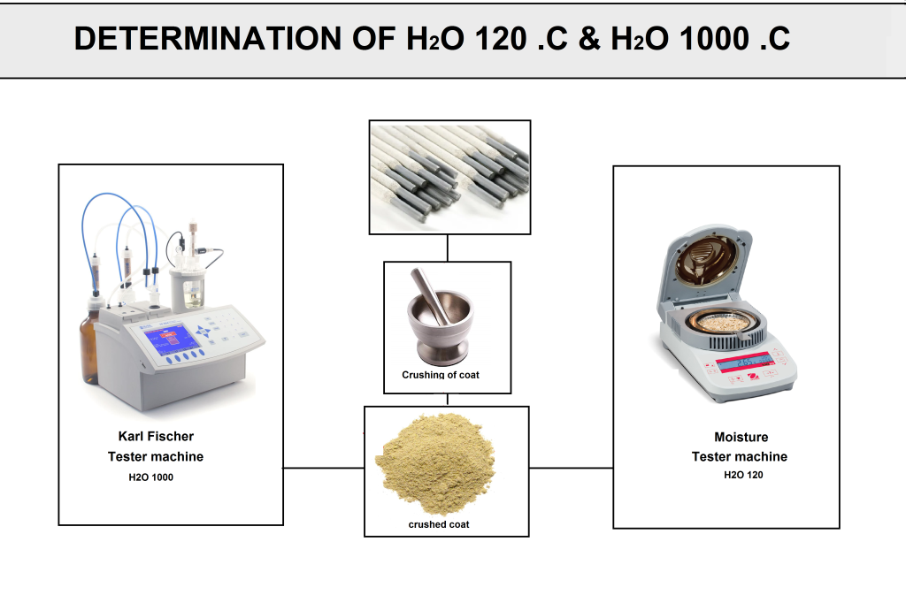
5-3) Physic-Chemical Tests:
Other parameters that affect the quality of raw materials are as follows
(if needed on the spec sheet)
•Density &Bulk density
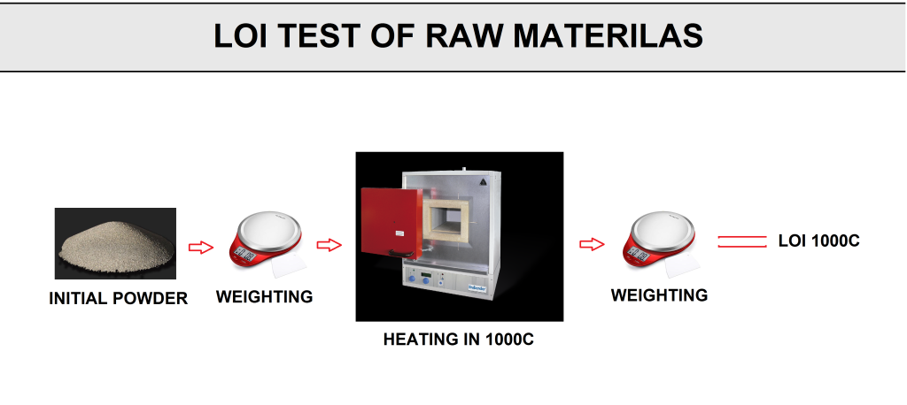
•LOI (loss of ignition)
•ASH
•Humidity or moisture (physical water & chemical water)
•Stabilize range (SR)
•Viscosity
•Baume
•Molar ratio
As an example, the moisture parameter of covered electrodes, measured as physical water (water released at 120°C), varies depending on the type of electrode. For basic electrodes like E7018, it should be less than 0.4% wt, whereas for cellulosic electrodes like E6010, it should be more than 4% wt. This parameter is also important for fluxes, which will be described in the relevant section.
In addition, viscosity and Baume are critical parameters for binders.These properties are controlled using specialized equipment.
The stabilization range is another critical parameter for some powders, such as low-carbon ferromanganese. It is measured using specific methods that analyze the amount of gas released and the degree of discoloration.
Required Tests for Raw Materials of Welding Consumables
Required Tests for Raw Materials of Welding Consumables
Required Tests for Raw Materials of Welding Consumables
5-4) Mechanical Tests:
These tests are used to determine the mechanical properties of primary coiled wire. In this test, the initial wire, with a diameter of 5.5 mm or 6.5 mm, is cut into 40 cm lengths and tested using a tensile testing machine. The results of the tensile test provide a reliable measure of the wire’s performance in the drawing and cutting process to achieve the desired diameter and length.
6) Welding Electrode Manufacturing Production Stages:
Read This Article and This to know more about the important parts of the welding electrode production line.
Welding Electrode manufacturing Flowchart
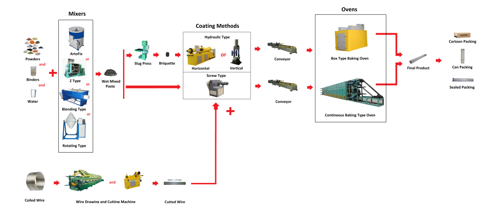
Welding Electrode manufacturing Flowchart
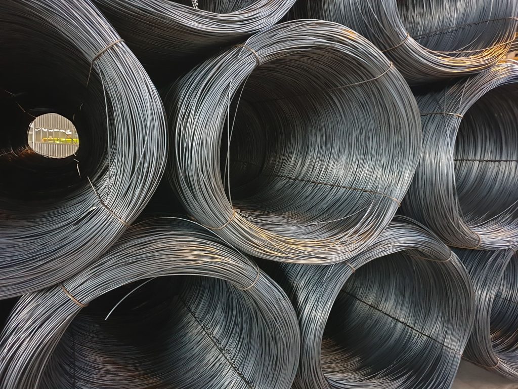
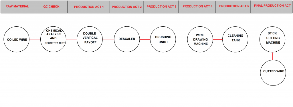
6-1) Drawing, Straightening, and Cutting:
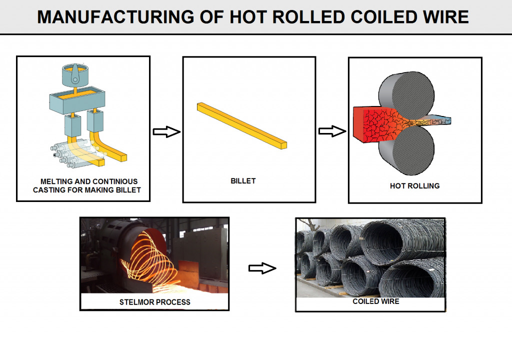
The primary feed for Welding Electrode Manufacturing is metal coils. These coils are mainly produced by the hot rolling method from ingots produced in the steel plant.
Coiled wires have different encodings in standards. These coils are classified into (non-low-medium-high) alloy steel groups as well as stainless and non-ferrous steel such as nickel, aluminum, cobalt, etc.
Coiled Wire Production as a Raw Material in Welding Electrode Manufacturing
Coiled wires have different encodings in standards. These coils are classified into (non-low-medium-high) alloy steel groups as well as stainless and non-ferrous steel such as nickel, aluminum, cobalt, etc.
The Carbon Steel SWRY11 wire in the JIS G3503 standard is one of the most widely used wires that can be used in the production of many electrodes, including E6013,E7018,E7024,E6010. Initial coils are usually are in one or two ton weights. The general steps of the Drawing process are illustrated in flowchart.
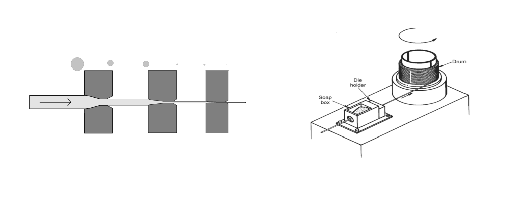
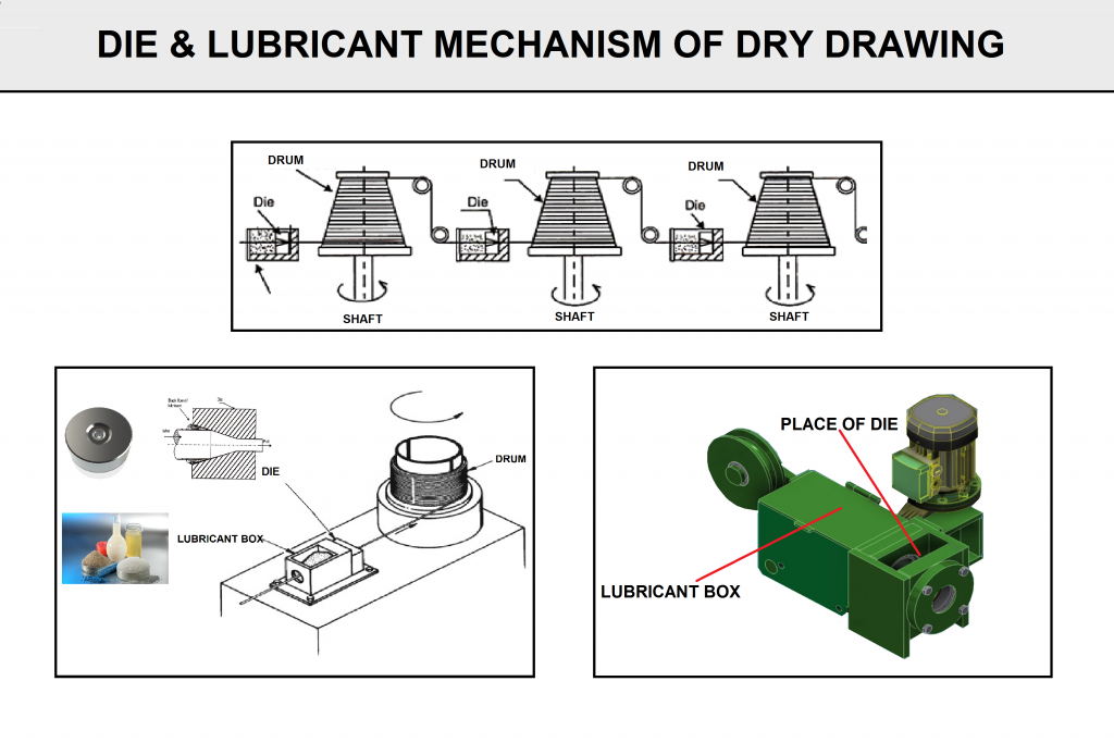
In recent years, advancements in technology have resulted in drawing machines with various mechanisms that significantly enhance the quality of the final wire. In general, dry drawing is commonly used in electrode production plants. The image below provides an overview of this process. For details on the latest technologies in this field, refer to the Morgan-Koch Company website.
Wire Drawing for Manufacturing of Welding Electrode
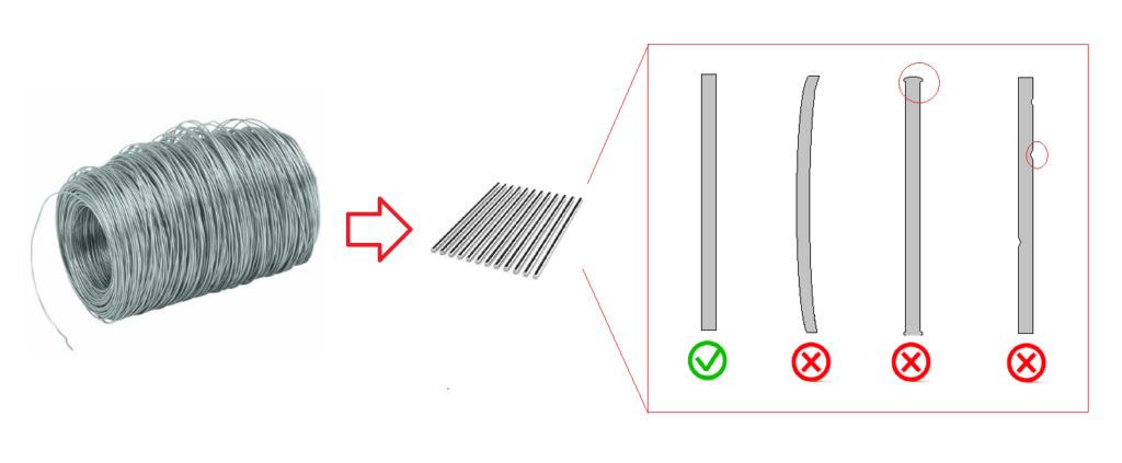
As mentioned in the flowchart, the output of the drawing and cutting process is the core wire used in the manufacturing of covered electrodes. The appearance characteristics of this core wire are critical; if they are not properly maintained, issues may arise during the pressing of the coating onto the wire’s surface. The primary issue is the wire becoming stuck in the transfer nozzle leading to the covering area.
Suitable Core Wire for Manufacturing Welding Electrodes
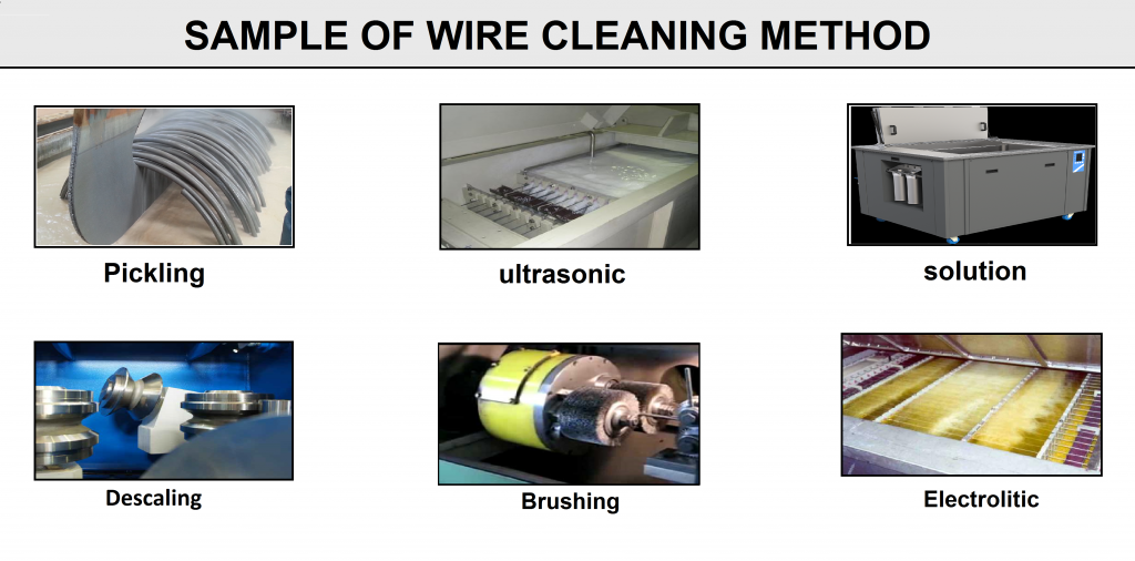
It is crucial that the wire is thoroughly cleaned after the drawing process is complete and cut to the appropriate length. When it comes to cleaning ferrous wires during the wire drawing process, there are a few key methods we use in the industry to ensure a clean, high-quality surface. Each method has its purpose depending on the condition of the wire and the type of contaminants we’re dealing with. Methods such as Acid cleaning, Mechanical Cleaning, and Washing in the Detergent tub, or Ultrasonic Cleaning before or during the process.
As mentioned earlier, the reduction of the wire diameter is achieved using wire drawing machinery. For example, in the SWRY11 wire drawing process to produce E7018 electrodes with a final diameter of 2.5 mm, the desired diameter can be achieved through six steps of drawing. It is also necessary to use different lubricants to reduce die friction with the wire, facilitate the drawing process, and extend the service life of the dies. Sodium and calcium-based lubricants are widely used in wire drawing.
Once the wire reaches the proper diameter, the wire straightening process is performed. The resulting wire must be free of bending and deflection. The final step is to cut the wire to the desired length. Wire lengths are typically 350 mm and 450 mm.
6-2) Dry & Wet-Mixing for Preparing The Flux
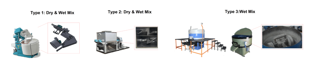
At this stage, all approved powders in the warehouse are weighed according to the formulation using either a manual or automatic system and then proceed to the dry mixing stage. The wet mixer may be separate from the dry mixer, or a single mixer can be used for both stages.
The duration of the dry mix depends on the type of mixer and the nature of the formulation. For some formula groups, extended mixing times can cause material adhesion, leading to mixing failures. However, for electrode types such as cellulosic electrodes, special attention must be given to the mixing conditions due to the significant physical differences between cellulose powder and metal powders like manganese. This ensures a homogeneously mixed flux.
The wet mix is achieved by adding a precise amount of binder and water to the dry powder mixture. The mixing times for both dry and wet processes are specified in the electrode manufacturing instructions. The output of this stage is a paste-like flux.
Dry & Wet Mixer Types for Manufacturing Welding Electrode
6-3) Extruder
The extruder used in the manufacturing of covered welding stick electrodes is a specialized machine designed to uniformly coat a core wire with a flux-based material. The process begins with the feeding of the prepared coating mixture—comprising powdered materials, binders, and liquids—into a hopper. A screw conveyor or hydraulic plunger then compresses and pushes the mixture forward under controlled pressure, ensuring uniform consistency. Simultaneously, the core wire is fed into the extruder through a precise alignment mechanism. The coating is applied as the wire passes through a specially designed die, which shapes the material to achieve the desired thickness and ensures uniform adhesion. Excess material is scraped off to maintain consistency in dimensions. Once coated, the wire exits the extrusion nozzle
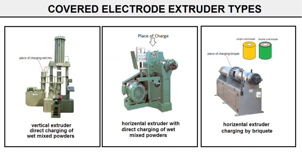
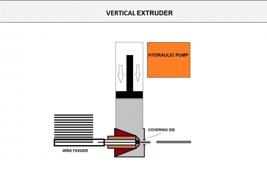
6-3-1) Vertical extruder
In this machine, the paste enters a cylindrical vertical chamber that directs it to the extrusion die. One advantage of this method is that a larger amount of paste can be used in a single charge of the device, which speeds up production. However, the drawback of this method is that it has a lower production rate.
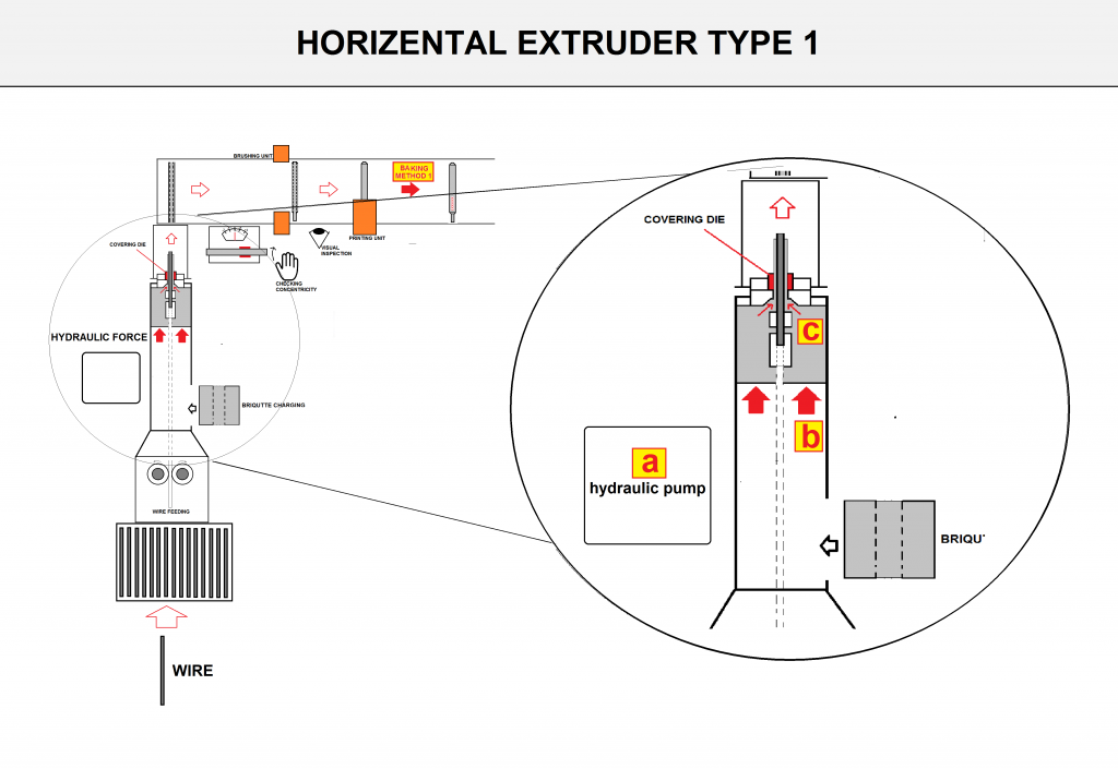
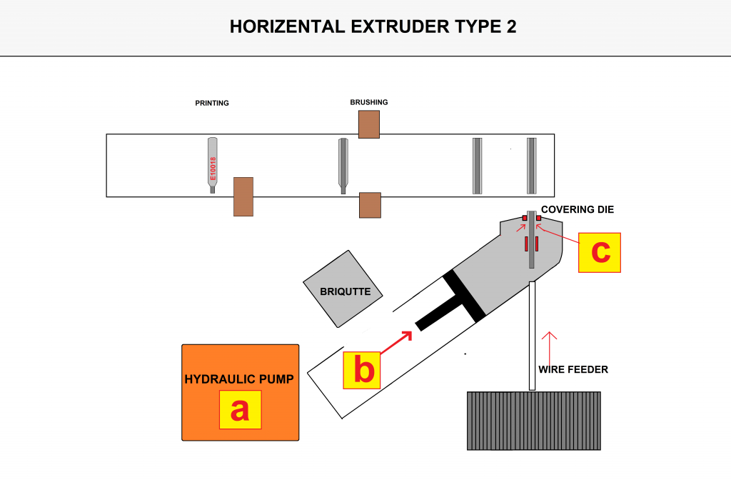
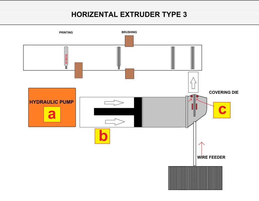
6-3-2) Horizontal extruder:
In this method, the paste from the wet mix is first inserted into a briquetting (slug) press, and then the prepared briquette is charged into the horizontal extruder.
The advantage of this method is a lower production rate coupled with higher precision. However, its disadvantage compared to the previous method is a slower overall production speed, because, unlike the previous method, a briquette-making step is required before using the extruder unit.
Types of electrode extruder machinery vary according to production requirements.
6-3-3) Mechanism of Cover Pressing on Wire:
In general, all extruder machines operate similarly, but they differ in how the paste is fed into the machine. Each device uses a die sized according to the required dimensions, and force is applied to the die in the extrusion chamber through an outlet nozzle. An overview of this process varies based on the type of coating.
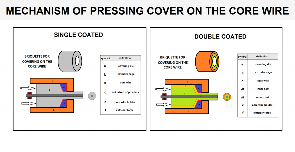
As shown above, there are two types of extruders for welding electrode manufacturing. Both models operate similarly by applying pressure behind the flux, thereby coating the wire’s surface.
The primary difference between the two models lies in the force applied to the flux. In the screw-type extruder, the applied force is relatively low, making it suitable for producing simple electrodes (e.g., E6013) in high volumes. In contrast, hydraulic extruders apply force via a hydraulic system, allowing for the production of more specialized electrodes.
Hydraulic extruders are designed in two orientations: vertical and horizontal. While the vertical model generally has a higher capacity, it can pose challenges in manufacturing certain types of covered electrodes.
The figures below show examples of both horizontal and vertical hydraulic and Screw extruders.
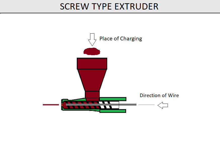
Screw Type extruder (Top View)
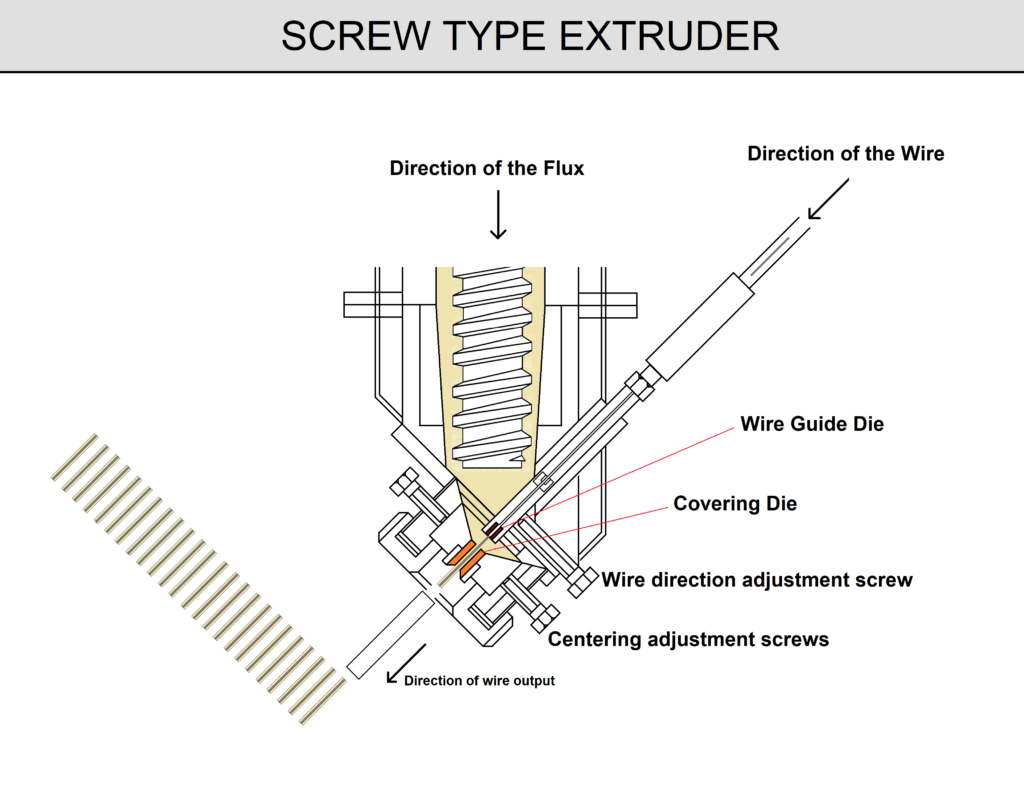
Screw Type extruder (Side View)
Hydraulic Horizontal extruders type 1 (Top View)
Hydraulic Horizontal Extruder Type 2 (Top View)
Hydraulic Horizontal Extruder Type 3 (Top View)
Hydraulic Vertical Extruder (Side View)
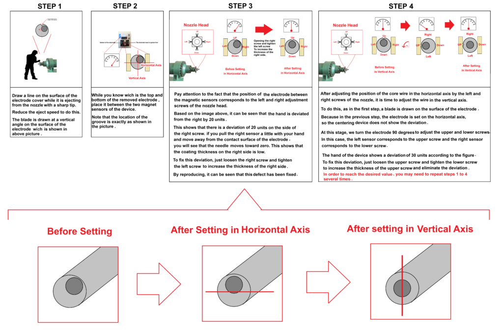
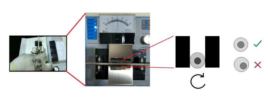
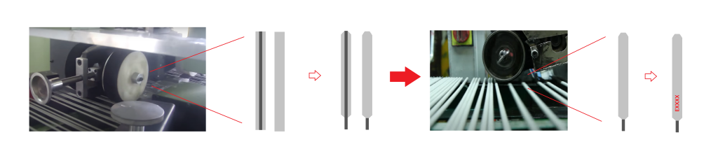
6-4) Centering & Brushing and Printing
After the extrusion process is applied to the wire, the pressing force propels the electrode onto a conveyor, moving it forward. At this stage, the operator inspects the concentricity of the coating using a specific testing machine. Next, the electrode proceeds through the tip and nip brushing unit, and finally, it is directed to the printing unit.
Usually, at the start of production, the core wire is not centered in the coating, which leads to the production of electrodes with suboptimal welding performance.
To properly align the wire in the center of the coating, the operator must adjust the nozzle’s horizontal and vertical axes using a simple yet effective method (illustrated in the figure below).
Method for Centering the Core Wire in the Electrode Coating
Eccentric Measurement Device for Checking the Centrally of Core Wire in Covered Electrodes
Head and Tail Brushing & Printing Units
At the end of the process, the electrode is placed on a carriage to rest and then transferred to the furnace, or it may go directly into the furnace via the same conveyor. These manufacturing procedures are carried out according to their specific instructions.
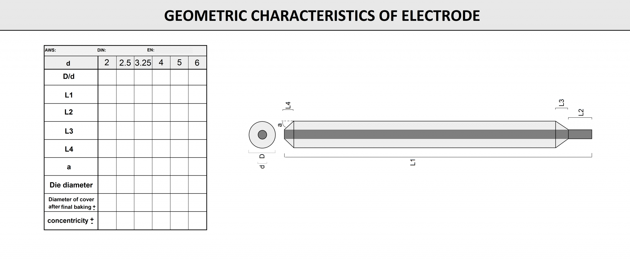
The physical properties of the electrode—such as wire concentricity, tip and nip geometry, and other parameters—are critical to the product’s final quality. All these parameters are listed on the electrode’s Physical Specifications Sheet for each product.
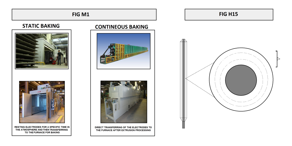
6-5) Baking
A critical factor in welding electrode baking is ensuring uniform heat distribution at all coating levels around the core wire. If baking is done improperly, the electrode’s surface may be fully baked while the inner layers remain underbaked. This process can be likened to baking a cake: each electrode requires a specific baking method depending on the characteristics of its coating.
Welding Electrode Baking Oven Types
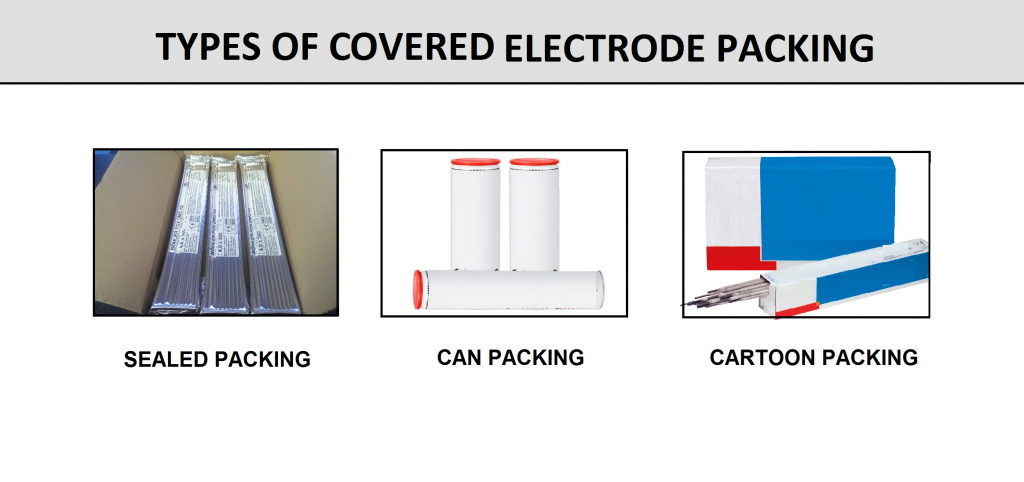
6-6) Packing
After baking, the electrodes are ready for packaging and delivery to the customer. The packaging requirements vary based on the electrode type. For instance, cellulosic electrodes must be stored in metal cans that help retain the coating’s moisture. By contrast, basic electrodes are typically packed under conditions that prevent any moisture ingress, such as sealed, moisture-resistant containers.
Another group of electrodes, such as rutile electrodes, are packaged in cardboard cartons and plastic laminates because they are less sensitive to moisture than basic electrodes. Finally, there are electrodes that require vacuum packaging due to the coating’s sensitivity to impact.
7) Verify the Quality of the Finished Product:
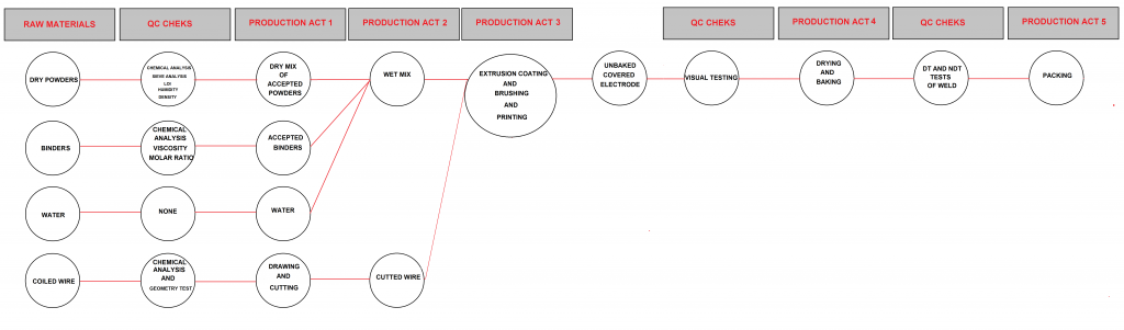
A critical aspect of the welding electrode manufacturing process is the quality plan, which covers every step. Quality checks are performed before, during, and after production. A summary of this quality plan is as follows:


The tests used to verify product quality are divided into two categories:
- Tests defined by standards
- Tests defined by the manufacturer
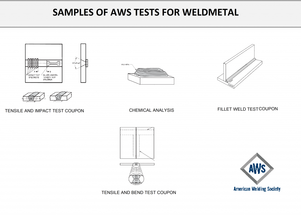
7-1) Tests defined by standards:
Valid international standards for each product provide precise definitions of the required tests and the acceptable result ranges. For example, see the figures below for the stainless steel covered electrode E308-L15, as defined by AWS standards.

7-2) Tests Defined by the Manufacture
Each manufacturer, in addition to aiming for test results within the standard’s optimal range, strives to incorporate specific features according to customer requirements. They also design tests based on these additional features.
Products are evaluated using a recognized method to verify their quality before final use. This concept underpins the standards for coated electrodes, which were developed by leading industrial nations. One of the most reputable standards is published by the American Welding Society (AWS). For instance, AWS A5.1 applies to E7018 electrodes and contains a complete description of the steps required for product quality testing.
7-3) Final Product Tests:
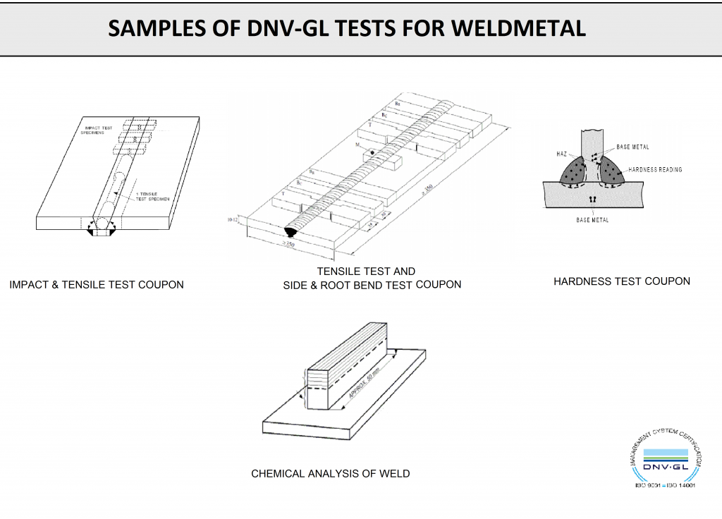
At this stage, all tests defined by the relevant standards, as well as any special-condition tests, must be performed. Different groups of welding electrodes are classified according to various standard systems. Among the most important international standards for welding electrodes are AWS, ISO, DIN, EN, and BS (see figures below).
AWS Test Sample
DNV GL Test Sample
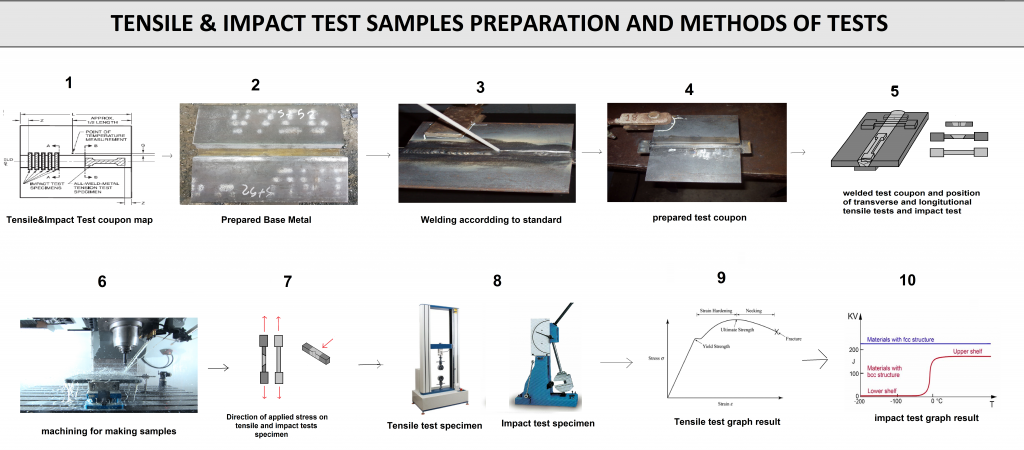
Tensile & Impact Tests
7-3-1) Humidiry of Electrode Covering:
The moisture content of electrodes, particularly after final baking, is a critical quality parameter. For basic electrodes, the moisture content should always remain below 0.6%, since excess moisture is generally detrimental. In contrast, cellulosic electrodes require a moisture content above 4%. This parameter is commonly referred to as H2O 120 (physical water released at 120 °C) and H2O 1000 (chemical water released at 1000 °C).
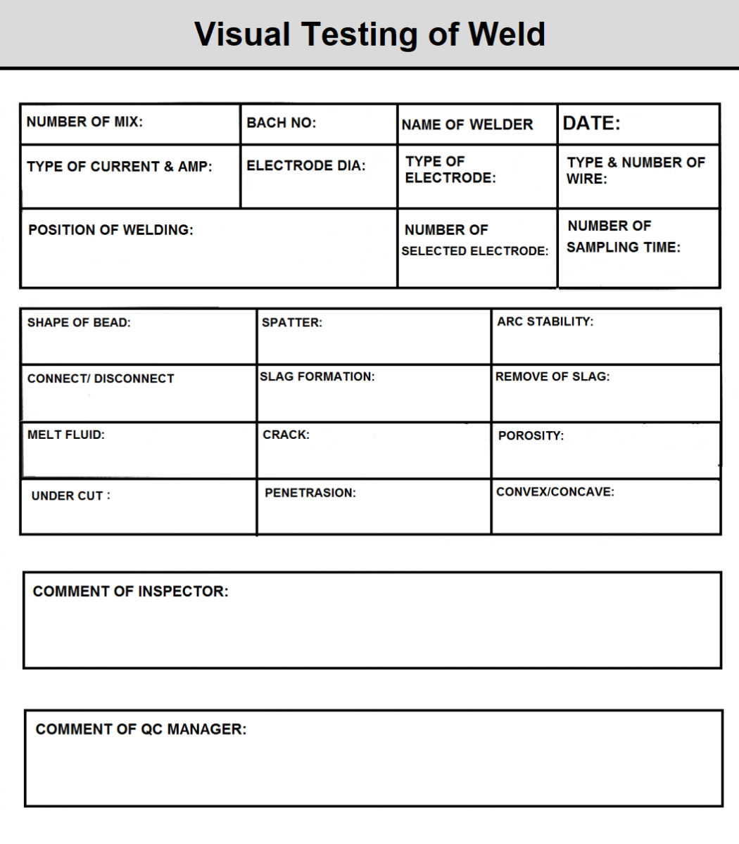
7-3-2) Welding Performance and Visual Test:
This test examines various welding parameters, including bead shape, penetration rate, weld convexity and concavity, slag detachment, porosity, gas holes, undercut, spatter, and more. The specific qualitative properties evaluated in this test depend significantly on the electrode type. For instance, low spatter and easy slag separation are critical for basic electrodes, while cellulosic electrodes emphasize a higher penetration rate. All pertinent welding control properties, according to electrode type, are included in the quality control unit’s documentation.
7-3-3) Destructive and Non-Destructive Tests:
As mentioned, each electrode has its own quality parameters defined in the relevant standard. The standard also specifies the acceptable limits for test results and explains how to perform these tests. The following sections describe these tests in detail.
7-3-3-1) Destructive test of weld metal:
.Tensile test
.Impact test
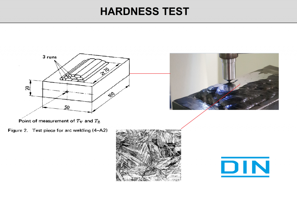
.Hardness test
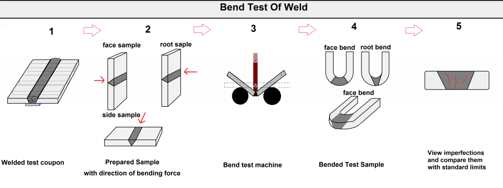
.Bend test
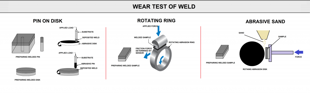
.Wear test
.Fatigue test
.CTOD
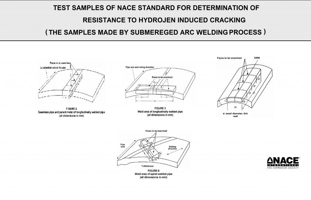
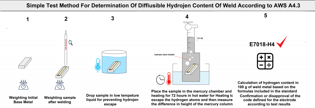
.Hydrogen tests
Tensile & Impact Tests
Hardness Test
Bend Test of Weld
Wear Test of Weld
Hydrogen Test of Weld
7-3-3-2) Non Destructive test of weld metal:
.VT
.PT
.MT
.UT
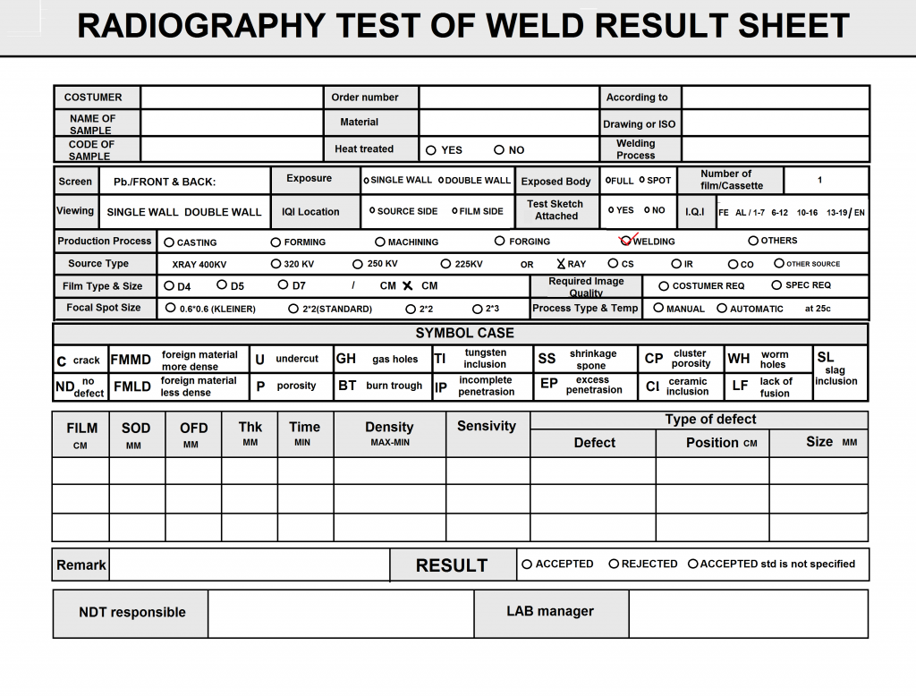
.RT
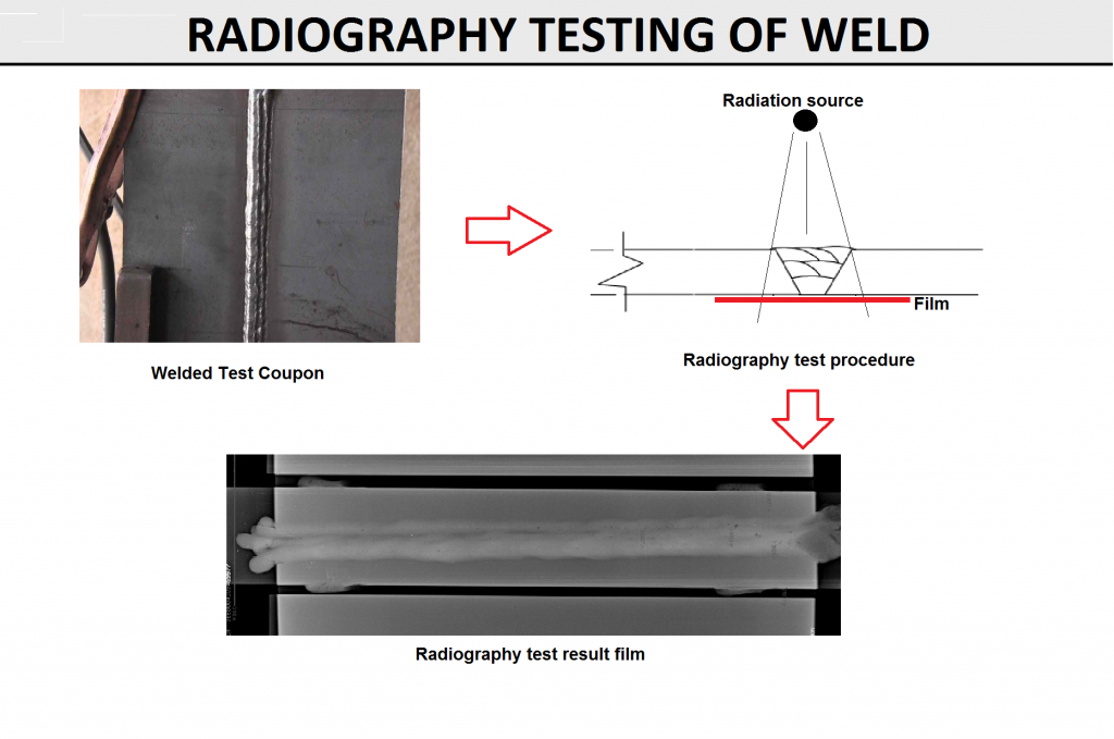
FIG S1
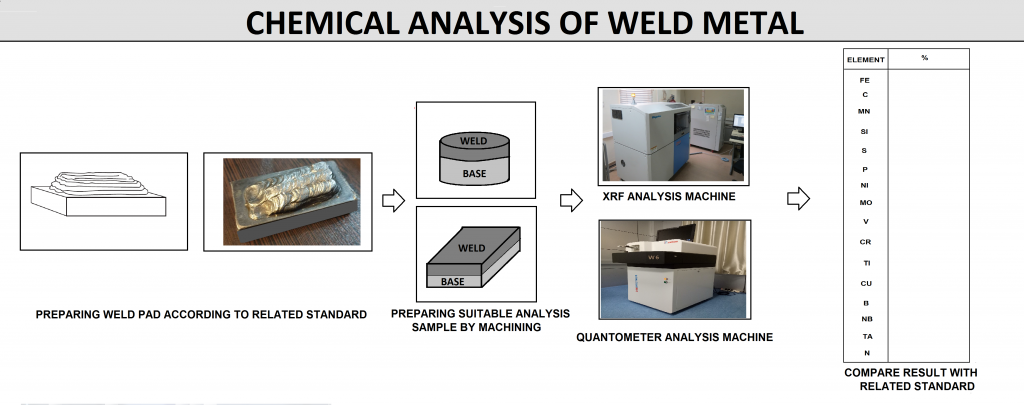
7-4) Chemical and Phase Analysis of Weld Metal:
.XRF (figure Z1).
.XRD
.CS (Carbon & Sulphur).
.Atomic Absorption.
.ON (Oxygen & Nitrogen )
.Spectrophotometry (figure Z1)
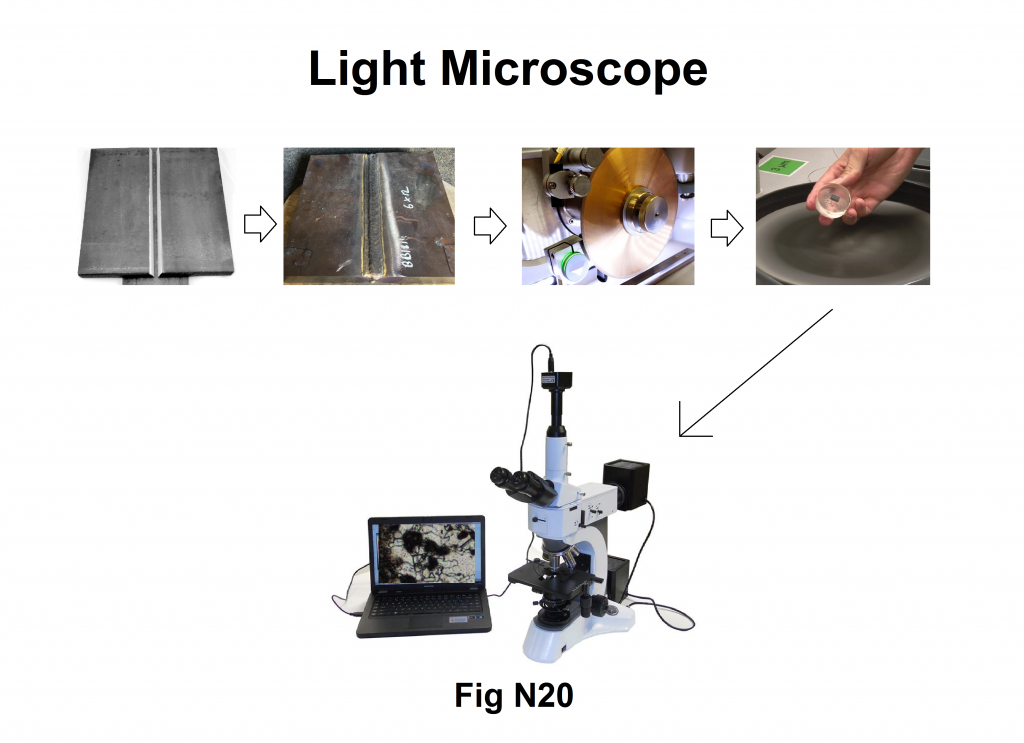
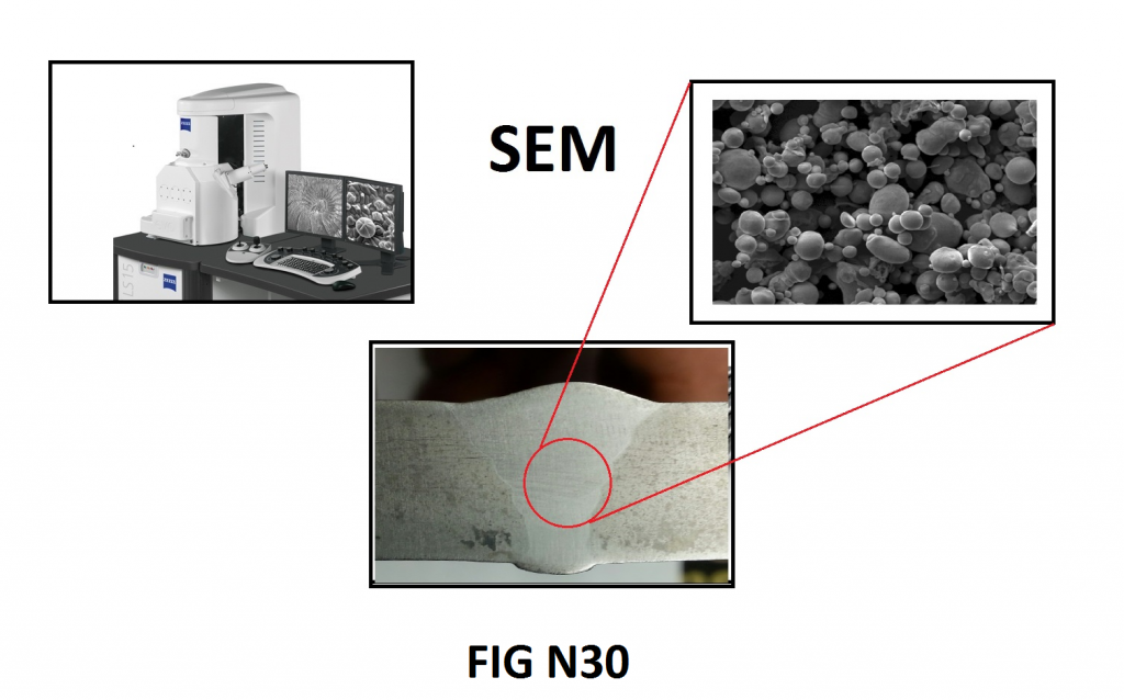
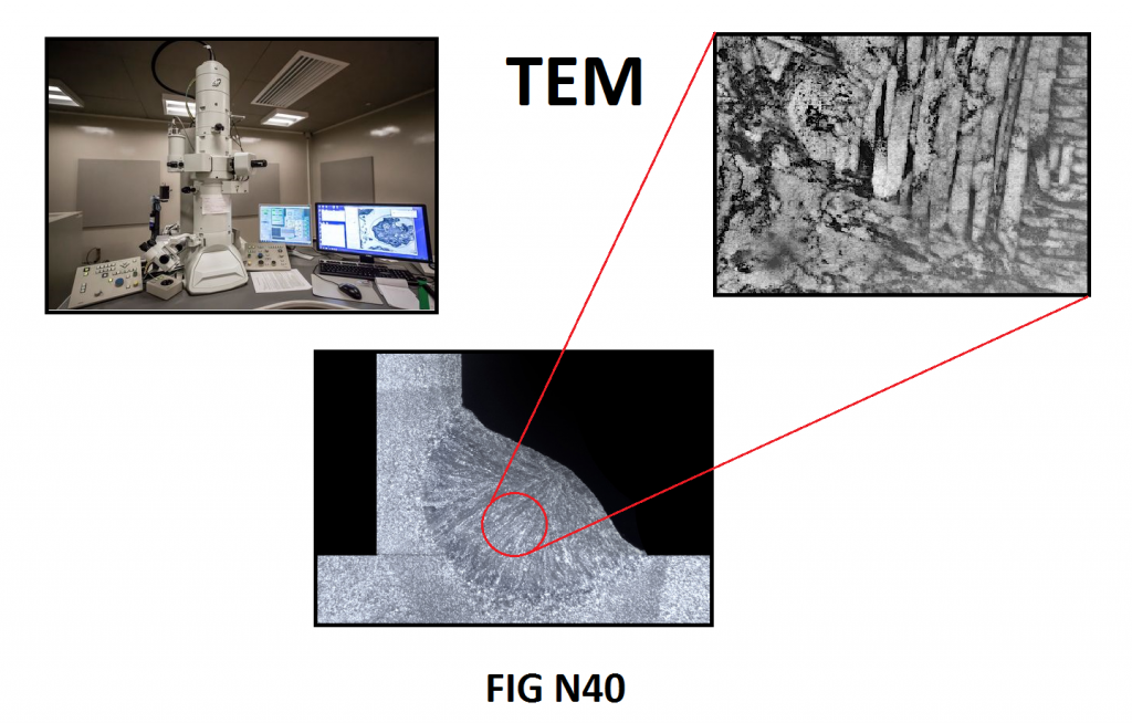
7-5) Microstructural Study Tests:
.Microstructural study with light microscope
.Microstructural study with SEM
.Microstructural study with TEM
7-6) Corrosion and Erosion Tests
These tests vary, and only those defined by the relevant standards or specifically required by the customer must be performed.
Note:
Producers do not need to purchase all of this testing equipment; they can outsource these tests to specialized laboratories.
In implementing the quality management system, WESPEC is fully responsible for determining the sampling frequency, reporting, and refining the test results.