Welding Electrode Approval
As a producer or even as a consumer of welding electrodes, it is necessary to know whether this product has the right quality or not. The first and easiest way to determine the quality is welding in the flat position, but this is the first step and it is necessary to determine the exact quality of the welding electrode according to the principles set by valid international standards.
In order to perform these tests, it is necessary to increase your knowledge about them. This article tries to share information about it.
In this article, Basic electrode E7018-H8 was tested as a sample.
Initial Review
Check the Initial Technical Specifications
Welding in a Flat and Vertical-Up Position
Choosing the Standard and Identifying the Required Tests
Conducting Tests
Chemical Analysis of the Weld Metal
Radiography Test of Weld
All Weld Metal Tension Test
Impact Test of Weld
Fillet Weld Test
Moisture Test of Cover
Hydrogen Diffusion of Weld Metal Test
Initial Review
In the first step, it is necessary to pay attention to the packaging of the electrode. Nowadays, electrodes are packed in different types. It is necessary to have the quality of the packaging without any tears or breaks. Electrodes will usually be damaged if they are packed incorrectly.
As mentioned, the packaging of the electrodes is different depending on their type. For example, cellulose electrodes are sold in a metal can packaging. This is because the humidity of the coating is maintained and the necessary properties for welding cellulose electrodes remain inside the coating. Therefore, when buying cellulose electrodes, pay attention to the absence of any damage in the metal can.
Another group of electrodes that absorb moisture, such as Basic electrodes, are packed in cartons or vacuum. In the case of vacuum packaging, the electrode is not re-baking by the consumer, but in the case of cardboard packaging, re-baking by the customer is necessary. For example, the E7018 electrode needs 400 degrees for one hour or 350 degrees for 2 hours.
Also, packaging with plastic boxes is done in another group of the electrodes to prevent damage to the coating and also Diffiution of the moisture. Vacuum packaging is also common for expensive electrodes such as ENI-CI to prevent damage to their coating.
Cheap carton packaging is also common for rutile electrodes such as E6013.It is common to use clear nylons in this type of packaging for added protection.
Types of Electrode Packaging

After ensuring proper packaging, it is time to check the appearance of the electrode. In general, the welding electrode has a tip with a 45-degree conic, and 18 to 23 cm of uncoated wire can be seen in the gripper part. Usually, in different markets, when talking about the diameter of the electrode, it means the diameter of the wire and not the coating. The diameter of the electrode coating or actually the ratio of the coating to the wire is part of the technical knowledge that companies use in the production of this product.
Electrode Geometry

Pay attention to the following points when checking the appearance of the electrode:
It is necessary that the electrode does not have any cracks on the coating. Any convexity and concavity on the cover are not allowed. Seeing the cover being removed from the wire will not allow its use. The presence of any rust on the wire is also not suitable.
Another experimental test that can determine the strength of the electrode coating is to drop the electrode on the ground from the height of your knee. If the coating separates from somewhere other than the top and bottom of the electrode, the strength of the coating is not suitable.
Proper Appearance of the Welding Electrode

Appearance Problems of the Electrode Coating

There is also a method that can determine the moisture level of the cover approximately by holding 10 electrodes in your hands and shaking them together. If the sound created due to the collision of the electrodes is muffled, the electrode has high humidity in its coating, but if it has a sound like the collision of metals, it has a suitable electrode coating.
Experimental Test of Electrode Coating Moisture

Check the initial technical specifications
it is necessary to pay attention to the specifications announced by the manufacturer. These specifications are stated on the electrode carton and also in the manufacturer’s catalog.
Usually, on the carton, there are specifications including the brand name of the product, the relevant code in different standards and recommendations for welding, including the type of current and amperage, and the temperature and time conditions for re-baking. If you do not find these specifications, refer to the product catalog in the handbook or the manufacturer’s website.
Technical Specifications Included On The Electrode Carton

Electrode manufacturers usually state the technical specifications of their products in a sheet. This document contains standard product codes in reference to standards, including AWS, DIN, EN, and ISO. The institutions from which the manufacturer has received approval for this product are also stated in this sheet. Institutions like GL.
In the following, the chemical analysis of the pure weld metal is stated and after that, the mechanical properties of the weld metal are announced. Other information includes the type and amount of the current for each electrode diameter and the maintenance and Re-Baking conditions of the electrode.
Technical Specifications Announced by the Manufacturer in Product Introduction

Welding in a Flat and Vertical Up Position
After the initial inspection of the appearance specifications, it is time to weld in a flat position. Welding in a flat position and according to the current recommended by the manufacturer gives the consumer a good view of the quality of this product. To perform this test, it is necessary that the material of the sheet used for welding is compatible with the welding electrode.
Welding Performance in Flat Position

In relation to this product, it is necessary to perform welding in the Vertical-Up position. The welding current in this position is lower than in the flat position.
Welding Performance in Vertical-Up Position

It is necessary to pay attention to a series of general points at first glance, such as the shape of beads, slag removal, spatter, and the absence of defects that can be traced with the eye, such as cracks and gas bubbles. Further, for a more detailed investigation, it is necessary to perform a visual inspection of the weld according to the items mentioned in the form below.
Welding Performance in a Flat Position Quality Report

Choosing the standard and identifying the required tests
After examining the electrode in the flat and vertical-up position, it is time for a specialized examination. To start this work, pay attention to the technical sheet of the product. Look at the opening table and find the relevant standards. According to this table, three standards can be seen. Our suggestion for initial review is AWS A5.1, prepared by the American Welding Society. Pay attention to this point, if the properties of this standard are reached, then the specifications of other standards will also comply. In addition, this standard is widely accepted in the world.
Technical Specifications of the Welding Electrode, Provided by the Manufacturer

American Welding Society Standard for E7018 Welding Electrode

The naming of this product in the standard according to an instruction made, these specifications are stated on page number 27 of this standard.
E7018 Classification

You may be a little confused when facing this standard at the first step. The volume of information seems very large. But you have to learn how to extract the information you need. After a few times, extracting the information will be easy.
In the initial pages of the standard, you will find the electrode classification table. Look for the 7018 electrode. In this table, the type of electrode coating, welding position, and type of welding current are stated. It is mentioned at the bottom of the table that the technical specifications of the product are explained in other tables.
Welding Electrode Classification in AWS A5.1

In the continuation of the standard, look for the table of required tests. This is table number four.This table specifies exactly all the required tests for each product and according to their diameter.
Require Test for E7018 Welding Electrode in AWS A5.1

According to this table, for the E7018 electrode, chemical analysis test, radiography test, tensile test of weld metal, impact test, fillet test, and moisture test are required. Also, for the E7018-H4R electrode, hydrogen tests, and moisture resistance tests are also required.
As can be seen in the table, it is not necessary to perform all these tests for all diameters. To check an electrode, it is suggested to check the diameter which requires all the tests. for this product, All tests are required for 4 mm diameter. And we consider this diameter for testing.
Conducting Tests
After the initial inspection of the welding electrode and performing operator tests in flat, Vertical-up, and overhead, it is time to perform quality tests determined by the standard. According to the standard of the American Welding Society, as stated in the table above, the following tests are required to check the accuracy of the electrode quality:
Chemical Analysis
Radiographic Test
All-Weld-Metal Tension Test
Impact Test
Fillet Weld Test
Moisture Test
Hydrogen Diffusion of Weld Metal Test
A test plate is prepared for the chemical analysis test, a test plate is prepared for the radiography, tensile, and impact tests, and a test plate is also prepared for the filet test.
Chemical Analysis of the Weld Metal
For detailed information on how to make a sample, refer to page 8 of the AWS A5.1 standard. To perform this test for this electrode, it is necessary to prepare a plate with a thickness of 10 mm and a length and width of 100 mm. The material of the sheet is also stated according to table 5 page 14 of the standard, and we have adapted ST52 steel to this table.
To make a test plate for chemical analysis, it is enough to weld three welding passes together. These three passes form one layer, and in the same way, we create another 3 layers, and finally 4 layers are created.
It is not necessary to pay attention to the inter-pass temperature because it does not affect the result of the chemical analysis.
Performing Chemical Analysis of Weld Metal

According to the figure above, it is possible to perform the chemical analysis test by both of the above methods. In this test, the quantometry method was used, and As can be seen, the test result confirms the limits of the AWS A5.1 standard.
Lab Report for Chemical Analysis of Weld Metal

Chemical Analysis of Weld Metal Limitation in AWS A5.1

Radiography Test of Weld
A test plate is prepared to perform radiographic, tensile, and impact tests. In fact, after welding to make the test plate, and performing the radiographic test, if it is confirmed, the tension and impact sample will be prepared from this test plate.
In fact, by performing a radiographic test, the quality of the weld metal is ensured under the specified conditions, and then the mechanical properties of the weld metal are determined by performing tension and impact tests.
The general process of sample preparation and testing is as shown below:
The Process of Sample Preparation and Radiography Test

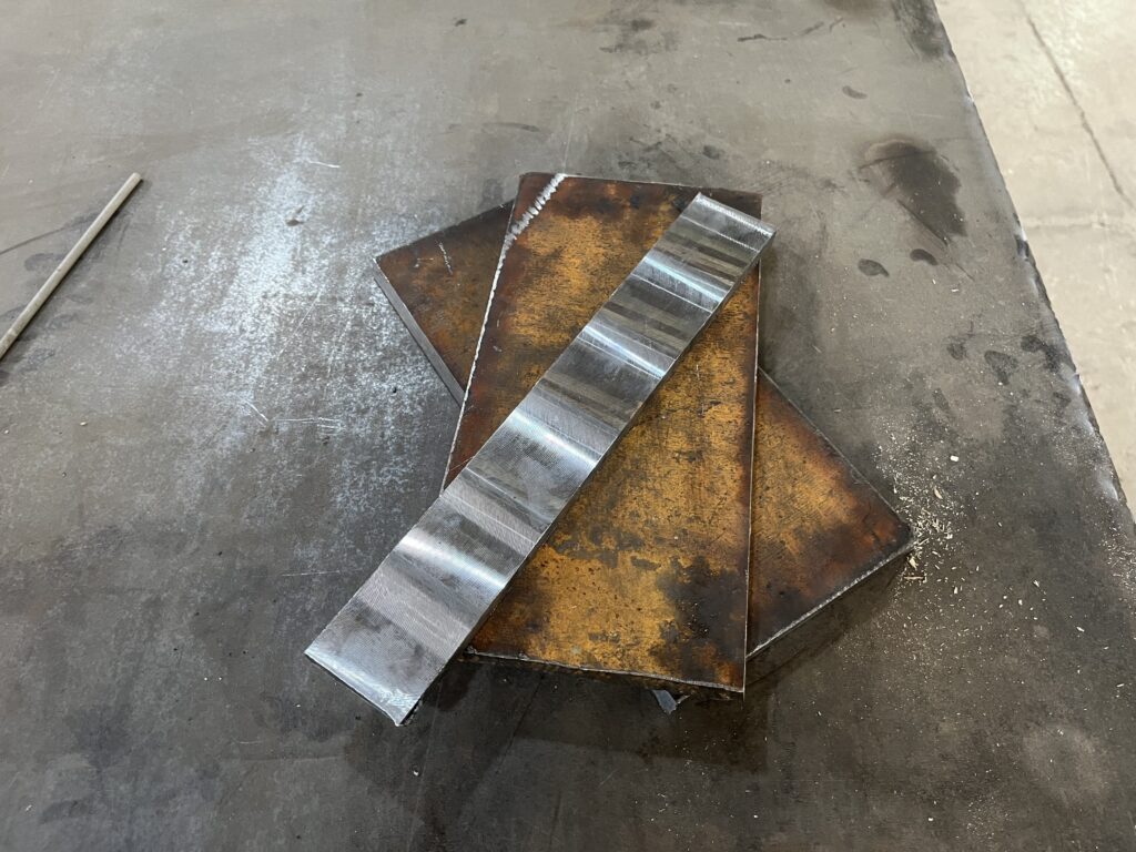
The process of welding and test sample preparation includes technical points. In the first step, we have to choose the base metal material. This material is selected according to the previous test of ST52 steel.
The next step is cutting and making both sides of the test plate and its back strip according to the dimensions determined by the AWS A5.1 standard. For this purpose, after making sure of the grade of the sheet by performing a portable metal analyzer, cutting is done with the air cutting process. Since this process introduces a lot of heat to the edges, in the next step, We use a lathe that generates a little heat in the cutting area for bevelling.
The Process of Test Plate Preparation

Dimension of the Test Plate for E7018 , 4 mm

welding test plate
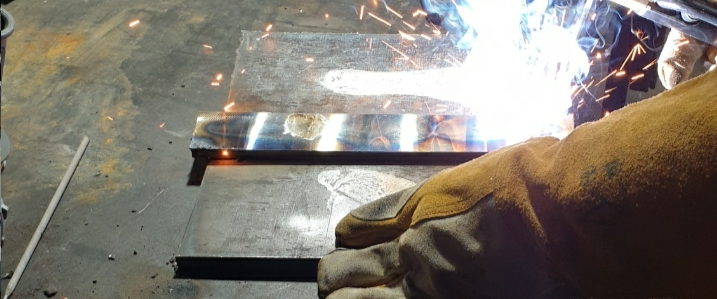
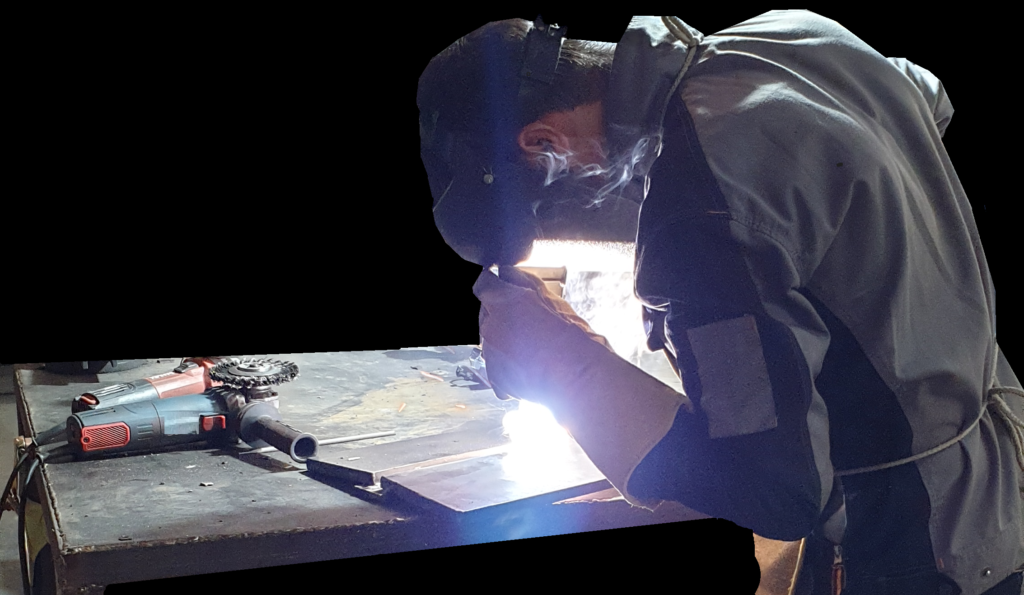
In order to weld the test plate, it is necessary to provide the requirements for this work. Safety is the first issue.
Safety clothing is very important. After that, the welding machine is ensured. It is also very important to use a suitable ventilation system during welding. A suitable table for welding is also very important. The items required to do this work are as shown below.
The Essentials of Welding Test Plate

Electrode 7018 is sold in two ways. If the electrode has a sealed package, it does not need to be rebaked, but if it is a cartoon package, the rebaking is done for 1 hour at 400 degrees. This is the recommendation given by the manufacturer in the catalog. According to the manufacturer’s guide, the welding machine is set to 170 amps with positive direct polarity.This means that the positive wire is connected to the electrode and the negative wire is connected to the part.
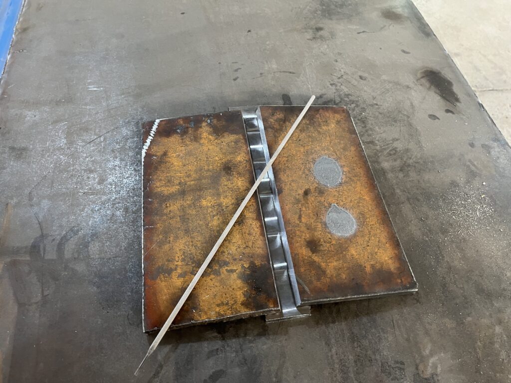
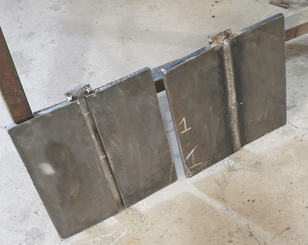
In order to start welding, it is necessary to assemble the test plate according to the connection plan. We assemble the part by making a welding spot and connecting the back strip to both sides of the test sample to start welding and heating the part to 100 degrees.
Welding is done in a flat position with a hand angle of 75 degrees and it is done by forehand technique. In forehand welding, the welding electrode moves in the direction of the weld progression. In backhand welding, the welding electrode moves in the opposite direction of the weld progression.
Welding Position and Technique

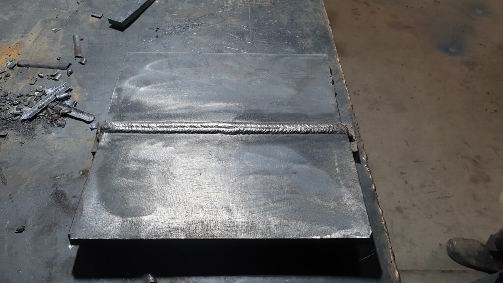
Welding requires a special technique. This technique is according to the figure below, we first start the welding pass A from one end of the piece and finish it until the middle of the piece. After welding, we completely clean the welding slag with tools. After cleaning, we start welding pass B from the end of pass A and continue to the end of the piece. At the end of each pass, cleaning is done until the welding is completed. At the end of welding pass B, we turn the piece 180 degrees and weld pass C, and then we make pass D. This process is done until the end of filling the groove.
Welding Technique for Making AWS A5.1 Test Plate

As can be seen in the above figure, during the assembly of the test plate, 5 degrees of deviation is deliberately applied to the sheets so that after the end of welding, due to the shrinkage after the piece cools down, the deviation angle of the sheets becomes zero.
Welding is done in 6 layers and each layer includes two passes. For example, passes A and B form a complete pass, and sets A, B, C, and D form the first layer.
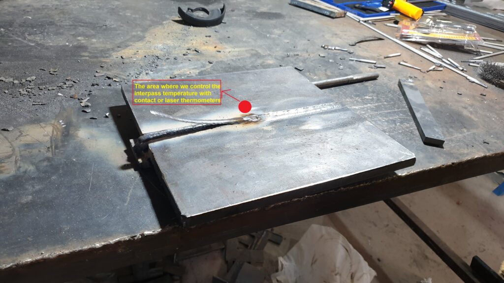
A very important point that must be observed during welding is to pay attention to the temperature between the passes. This temperature must be between 100 and 150 degrees and is measured by a thermometer at a certain point of the piece.
Passes and Layers Created in the Test Plate According to the AWS A5.1 Standard

In the pictures below, you can see the process of welding and preparing the test plate:
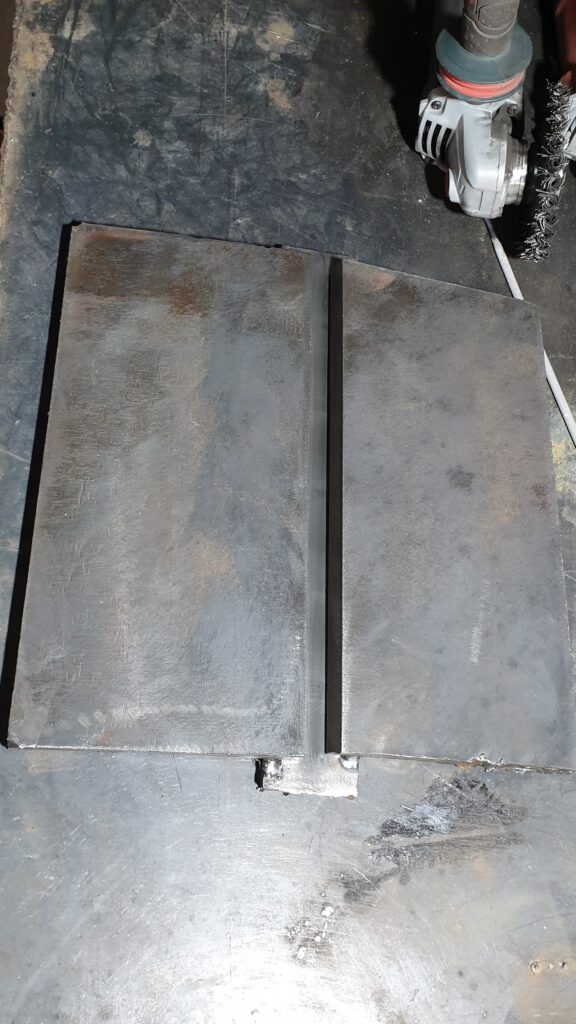
According to the image at the beginning of the text, which describes the process of sample preparation and radiographic testing, After welding and cooling the part, it is time for turning and preparation for the radiography test. To do this, first remove the back strip of the part and then make the level surface of the welding bead with the surface of the part. Also, both sides of the piece are cut to perform the radiographic test. Only the welding area should be radiographed so that tensile and impact samples can be prepared if there are no defects.
The radiography test is performed on the plate by a reputable laboratory and the result is shown in the test sheet as follows:
Radiography Film for Welded Test Plate of E7018, 4mm

Radiography Test Result for E7018 , 4mm Test Plate

As can be seen in the test result sheet, the method of performing this test is the ASME SECTION V, ASTM E94 standard, and the reference is the AWS A5.1 standard. Also, on pages 17 and 18 of the A5.1 standard, the acceptable limits for certain types of defects are stated.
In the test we performed, no defects were observed in the welding line, but there may be defects in a plate test that are within the standard acceptance range.
In this case, after performing the test and viewing the radiographic film, the commentator will express her opinion regarding the approval or rejection of the test.
Now that the result of the radiography test has confirmed that there is no defect in the weld line, it is time to check the mechanical properties of the weld metal by performing tension and impact tests.
All Weld Metal Tension Test
After radiography, the test sample is sent to the machining department to prepare one tensile test sample and 5 impact test samples. The important point is that if there are defects in the weld and its position is identified by radiography, it is necessary to pay attention to prototyping so that these defects are not included in the sample.
The exact dimensions and size of the test samples are stated in the AWS A5.1 standard, and the sample is made based on the specifications mentioned in the standard.
In the standard table, there are different dimensional specifications for each electrode diameter, and the diameter of 4 electrodes that we used in this test, is highlighted in the table.In the preparation of the plate, the dimensions mentioned in this table have been taken into consideration.
Location of Tensile and Impact Specimen in Test Plate

AWS A5.1 Standard for Preparing Tensile and Impact Specimen

Turning Process for Preparing Specimen

After preparing the tensile sample, it is sent to the mechanical laboratory to perform the test. The operator first marks the length of the gauge. For the sample we tested, the length of the gauge is 50 mm. This gauge is measured again after performing the test, and the percentage of length increase is known as the ELONGATION parameter in the introduction of product properties.
Before and After the Tensile Test

The test is performed in such a way that the operator places the sample between the upper and lower clips of the tensile test machine, and after tightening it, the operator orders the start of the test in the software that is connected to the machine. Before starting the test, the operator enters parameters such as the diameter of the area under tension, gauge length, and tension speed into the software.
At the start of the test, the stress-strain diagram is drawn at the same time as the tensile force is applied and the load cell is processed. This diagram is drawn up to the failure stage of the sample.
It is necessary to recognize the concepts of this diagram by the user. The tensile test is a common method used to determine the mechanical properties of materials, including steel. During the test, a steel specimen is subjected to an increasing tensile force until it reaches its breaking point. The test measures various parameters, such as the ultimate tensile strength, yield strength, and elongation.
The graph obtained from a tensile test of a steel specimen typically shows the relationship between stress (force per unit area) and strain (deformation per unit length). The graph consists of several distinct regions:
1. Elastic Region(B): At the beginning of the test, the steel specimen undergoes elastic deformation, meaning it can return to its original shape once the force is removed. In this region, the stress is directly proportional to the strain, resulting in a linear relationship on the graph.
2. Yield Point: As the force increases, the steel specimen reaches a point where it starts to exhibit plastic deformation. This is known as the yield point. The stress-strain curve may show a slight deviation from linearity at this point.
3. Plastic Deformation(C&D): Beyond the yield point, the steel specimen undergoes significant plastic deformation without a significant increase in stress. This region is characterized by strain hardening, where the material becomes stronger and more resistant to deformation.
4. Ultimate Tensile Strength (UTS POINT): The UTS is the maximum stress that the steel specimen can withstand before it breaks. It represents the highest point on the stress-strain curve.
5. Fracture(E): Once the steel specimen reaches its breaking point, it fractures, and the force decreases rapidly. This marks the end of the test.
The shape of the stress-strain curve can vary depending on the type of steel and its composition. It provides valuable information about the material’s strength, ductility, and overall mechanical behavior.
Tensile Test Performing Process

The result reported for our sample is as follows. According to the range of numbers described for the 7018 electrode, which is mentioned on page 4 of the standard, this test is within the standard range.
Tensile Test Limitation in AWS A5.1 Standard

Tensile Test Performing Process

Note: The problem that can be seen in some tensile test samples is the presence of a defect called a fish eye porosity in the cross-sectional area of failure. Fish eye porosity, also known as fish eye fracture, is a type of porosity that can be observed on the fracture surface of a tensile test specimen. It appears as small, rounded voids or craters scattered across the surface.
Fish eye porosity is typically caused by the presence of impurities or gas bubbles within the material. During the tensile test, as the specimen undergoes deformation and reaches its breaking point, these impurities or gas bubbles act as stress concentrators. They create localized areas of high stress, leading to the formation of voids or craters on the fracture surface.
The appearance of fish eye porosity can indicate the presence of defects or impurities in the material, which can affect its mechanical properties. In some cases, it may also suggest inadequate processing or improper handling of the material during manufacturing.
It is important to note that the presence of fish eye porosity does not necessarily mean that the material is defective or unusable. The severity and extent of the porosity, as well as its location within the specimen, should be evaluated in relation to the intended application and the material’s required performance criteria.
Fish Eye Porosity

Impact Test of Weld
The Charpy impact test of weld is a specific application of the Charpy impact test that focuses on evaluating the toughness and resistance to brittle fracture of a welded joint. In this test, a notched specimen, typically taken from the weld or heat-affected zone, is subjected to a sudden impact using a pendulum hammer. The energy absorbed by the specimen during fracture is measured, providing an indication of the weld’s ability to withstand sudden loading or impact.
By conducting the Charpy impact test on welds, engineers and inspectors can assess the quality and integrity of the weld joint. The test helps identify any potential weaknesses or defects in the weld, such as lack of fusion, porosity, or excessive hardness, which could compromise the structural integrity of the welded component. The results of the Charpy impact test of welds are used to ensure that welded structures meet the required safety standards and can withstand the expected service conditions.
Impact Test of Weld Metal Performing

In this test, 5 impact samples are extracted from inside the test plate according to the pictures by turning. The dimensions of this sample are 55 x 10 x 10 mm. These samples are made from both parts of the welded metal and the base.
According to the standard instructions, it is necessary to create a V-shaped groove in the middle of the weld metal, and for this, it is necessary to first etch the sample with a 3% nital solution so that when the weld metal is identified, a groove is created in the middle of it.
Impact Test of Weld Sample Preparation

Impact Test of Weld Sample Preparation

After creating a V-shaped groove in the middle of the weld metal of the impact samples, it is possible to perform the impact test. According to the standard instructions, the impact test for the weld metal obtained from the 7018 electrode is performed at a temperature of minus 30 degrees Celsius. They are placed in a solution in a chamber, and after the temperature of the samples reaches minus 30, using special pliers, the samples are placed in the place of the impact test and the test is performed.
Charpy Impact Test Cooling Chamber

According to the video above, after every impact on the sample, the indicator shows the impact energy number in joules.The samples may be separated due to impact or may remain connected. The place of detachment is always from the place of the V notch.The maximum and minimum values are removed from the 5 result and averaged from the remaining 3.The resulting number is known as the impact energy of the weld metal at a temperature of -30 c.
The results of the test we performed are stated in the test report sheet as follows. According to this result and based on table number 3 page 5 of the AWS 5.1 standard, this product has the properties of the E7018 electrode.
In the table that follows table number 3 in AWS A5.1, it is stated that if the sample reaches 27 joules at a temperature of -45 degrees, it can be classified in group E7018-1. According to the results obtained for this product, if we test it at a temperature of -45 degrees, it can reach the properties of 7018-1.
Charpy Impact Test Result for the Weld Metal , Made by E7018, 4mm

Limits for the Impact Test of the Weld Metal , Made by E7018, 4mm

Fillet Weld Test
In the AWS A5.1 Standard, the fillet weld test refers to a specific type of weld test that is conducted to evaluate the quality and strength of fillet welds. This test is performed according to the guidelines and specifications outlined in the AWS A5.1 Standard. The fillet weld test helps ensure that the welds meet the necessary criteria for strength, integrity, and performance.
Performing this test for the E7018 electrodes is a bit confusing and needs to be explained in more detail.
After preparing the sheet with appropriate dimensions and adjusting the connection plan, it is time for welding. First, we create two samples by welding in a Vertical-Up and OverHead position with the required amp according to the image below. Pay attention to the direction of welding and the end and restart of welding.
Require Specification for making Fillet Weld Test Sample According to the AWS A5.1

After welding, a visual inspection of the weld is done to check the possibility of cracks, slag, porosity, and overlap. There is no problem with the occurrence of an undercut defect if it is infrequent and with a depth of 0.8 mm. After the visual inspection, it is time to perform the macro test. To do this, a sample is extracted from the middle of the piece according to the image. The cut surface is completely polished and etched with a suitable solution. This is done because the amount of penetration of the weld and the bead geometry are completely checked.
Welding in Over-Head & Vertical-Up Position for Making fillet weld test Sample by E7018 , 4mm

Measurement of welding dimensions is done by a simple tool called gauge, and accurate measurement of geometric dimensions is also done by macrographic method.
Measuring Fillet Weld Dimensions by Gauge and Macrography Method

By measuring the dimensions by the mentioned methods, the results are compared with the AWS A5.1 standard. The resulting weld metal becomes concave or convex in the fillet weld, and it is convex for the E7018 weld metal. There are three main parameters in this test: Fillet Weld Size, Fillet Weld Legs, and Convexity.
First, the weld fillet size is measured, then we measure the maximum convexity parameter, and finally, the difference between the two weld legs is measured. Finally, the numbers are compared with the standard table described below.
Dimensional Specification of Fillet Weld in the AWS A5.1 Standard

The Required Dimensions of the Fillet Weld According to the AWS A5.1 Standard

Another test is placed in this category called the fillet weld fracture test. According to the AWS A5.1, the fillet weld fracture test is a method used to evaluate the quality and strength of a fillet weld joint. This test involves subjecting the weld to a force until it fractures. The purpose of this test is to assess the weld’s ability to withstand applied loads and to ensure that it meets the specified requirements for strength and integrity. The test is conducted in accordance with specific procedures outlined in AWS A5.1 to ensure consistency and accuracy in the evaluation process.
After applying force and breaking the weld, the broken surface is subjected to visual inspection. How to complete the test and the acceptance criteria are fully described on pages 21 and 22 of the AWS A5.1 Standard.
Fillet Weld Fracture Test

Moisture Test of Cover
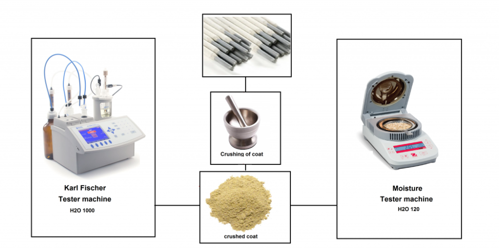
The moisture test of a welding electrode is a procedure used to determine the moisture content present in the electrode. This test is important because excessive moisture in the electrode can lead to various issues during welding, such as porosity, cracking, and reduced weld quality. The moisture test typically involves heating the electrode to a specific temperature and measuring the weight loss due to moisture evaporation. The results of the test help ensure that the electrode is dry and suitable for use in welding applications.
Water can be present in the flux due to various reasons, such as Manufacturing Processes and Storage and Handling.The presence of moisture in the electrode coating is divided into two types: water that comes out of the coating at a temperature of 120 degrees, which is known as physical water, and water that comes out at a temperature of 1000 degrees, which is called chemical water.
In order to measure the physical humidity, there is a simple and small device that is used by removing the cover from the wire and crushing it, and inserting it inside the device for 5 minutes at a temperature of 120 degrees. The mechanism of this device is to weigh the sample before and after heating. To measure the humidity of 1000 degrees, a more complex device called Carl Fischer is used, which measures humidity with a similar mechanism.
Moisture Test Methods for Welding Electrode Covering and Welding Flux
The AWS standard has given detailed explanations about this test on pages 22, 23, and 24. This part is based on the A4.4M standard (Standard Procedure for Determination of Moisture Content of Welding Fluxes and Welding Electrode Flux Coverings)
In this standard, the three concepts of As-Received, Conditioned, and As-Exposed are described before performing the humidity test and getting the results.
As-Received means that the welding electrode is tested immediately after it comes out of the package.
Conditioned means that the electrode has been rebaked and heated at a certain temperature and time before testing.
As-Exposed means that the electrode is intentionally exposed to moisture under defined conditions before testing.
It is emphasized that if the sample is placed in any of the above three methods, it must be mentioned in the result report.
In the table below, which is from the AWS standard, it states the acceptance limits of the test result under the mentioned conditions.
Moisture Content Limits According to the AWS A5.1

The electrode we tested had a result of 0.37 within the standard range for an E7018 electrode. If we want to add the (R) extension at the end of the code, which means moisture resistance, it is necessary to pass the results of the second part of the table. which means that the electrode is placed in a chamber with 80 to 85% humidity and at a temperature of 27 to 30 degrees for 9 hours before the test.
Hydrogen Diffusion of Weld Metal Test
Hydrogen diffusion of weld metal test is a method used to assess the presence and concentration of hydrogen in the weld metal. This test is important because excessive hydrogen can lead to hydrogen-induced cracking, also known as cold cracking, in the weld. The test involves extracting a sample of the weld metal and subjecting it to controlled conditions, such as elevated temperature and pressure, to promote the diffusion of hydrogen out of the sample. The amount of hydrogen diffused is then measured and compared to acceptable limits to determine the quality of the weld. This test helps ensure the integrity and reliability of welded structures.
The AWS A4.3 Standard has stated various methods for performing this test, some of these methods are simple and some are performed with advanced machines.
The picture below shows the simplest method described in this standard for measuring hydrogen in welded metal:
Hydrogen Diffusion in Weld Metal Measuring Test

According to the instructions mentioned on page 24 of the AWS A5.1 standard, it is necessary to inspect the smallest and largest diameter of the product for each electrode, and the work was done for the E7018 that we were inspecting.
The result of this test published by the laboratory shows that this product contains less than 8 milliliters of hydrogen per hundred grams of welded metal.
According to this result and based on the standard classification, the suffix H8 can be added to the end of the name of this electrode.
Hydrogen Diffusion in Weld Metal Classification According to the AWS A5.1
