Sub Merged Arc Welding Flux Manufacturing
2-1) Powder
2-2) Binder
INTRODUCTION
Welding Flux production process includes the following steps: Dry and Wet mixing based on a formula, Granulating, pre-baking, sieving, Baking. The grain size of the final product and shape condition of ingredients will be vary based on each welding flux.
Submerged Arc Welding was discovered in the year 1935 by Rothermund and Jones, Kennedy. This welding can be operated in semi-automatic mode otherwise in automatic mode. But generally, the operation of this SAW can be done in automatic mode. The submerged-arc welding method is fixed and extremely adaptable. This kind of welding involves in arranging the arc among a constantly fed electrode as well as the workpiece. A layer of powdered flux generates a protecting gas shield as well as a slag to protect the weld region. The arc can be submerged below the flux layer & in general, is not noticeable throughout the welding process. In this, the weld quality is extensively influenced by the submerged arc welding fluxe quality.
In This Section, we describe the process of manufacturing agglomerated arc welding fluxes.
SAW FLUX PRODUCTION FLOWCHART
1) Review Relevant Product Standards
It is necessary to find out what are the standards for determining the quality of a product. This is because WESPEC guarantees the final quality of the product and its compliance with relevant standards.For this flux the relevant standards are as follows. Each of these standards has specific guidelines for conducting quality assurance tests.
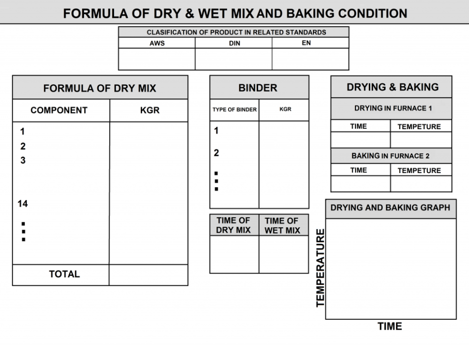
2) Review Relevant Formulation & Specification Of Product
Each product has its own production formulation and also instruction for manufacturing process(figure I1).In addition, the specifications of the raw materials are presented in the SPEC sheet as belows.
FIG I1
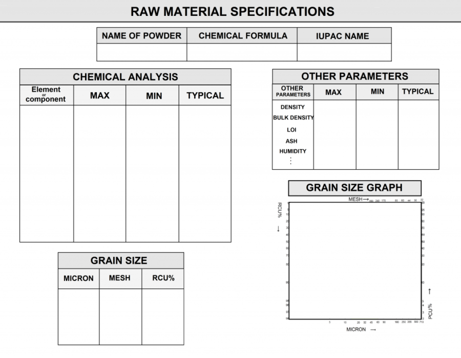
2-1) Powder (Fig B):
Each welding flux can contain an average, 10 to 20 types of Minerals, Chemicals, Metals, Ferroalloys. The specification sheet of each powder consist properties of the powder, including chemical analysis, sieve analysis, density, humidity, LOI, ASH that are shown in the related figure.
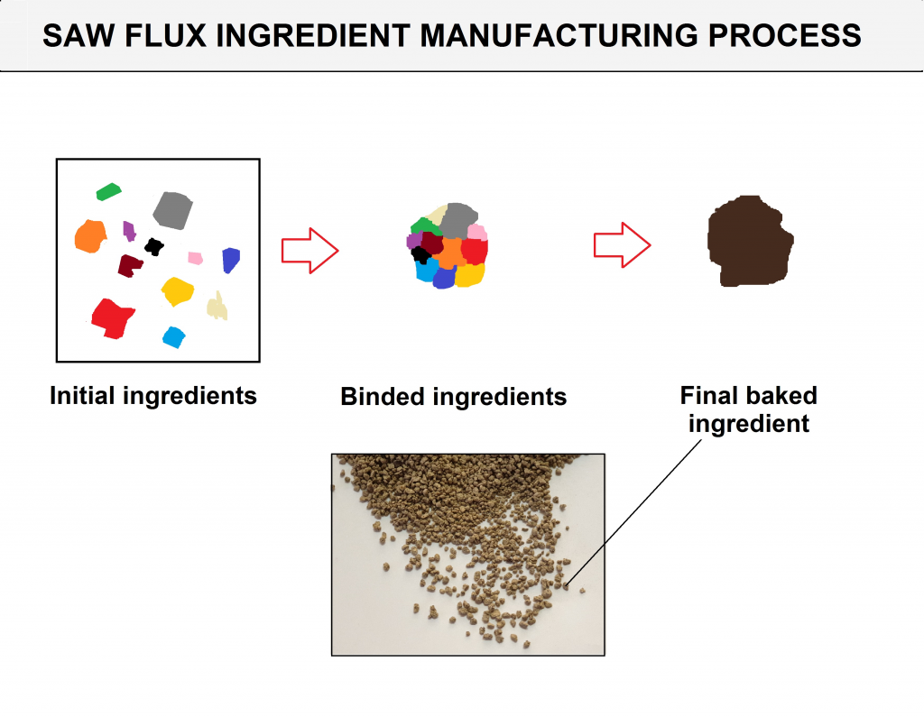
It should be noted that even a final grain flux must be included all the initial powders. This characteristic will result in the welding process having all the raw materials present in the weld pool and they will do their duties according to their functions including Alloying, Slag making, Refining (figure I3).
FIG B
2-2) Binder (Fig C):
The main task of the binder is to paste the raw material particles together to make a welding flux ingredient. These groups of materials are mainly from sodium and potassium silicate compounds.
FIG C
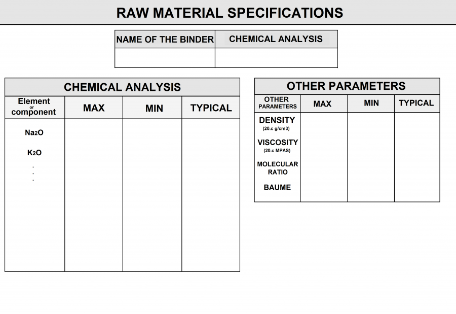
FIG I3
3) Prepare Raw Materials Based On Spec:
WESPEC has information about all approved suppliers of raw material around the world. We can advise you in purchasing raw materials based on spec.
4) Qc Of Raw Materials Before Manufacturing:
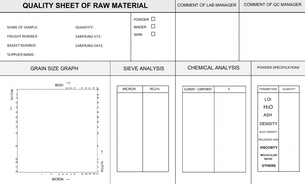
The verification of the quality of raw material requires relevant tests. In fact, it can be better to say that by checking one by one item listed on the raw material spec sheet. The procedure is that after preparing the powder according to the spec, the prepared powders are referred to the laboratory in order to determine their quality. These results will be aggregated into one sheet for the final decision (figure D).
FIG D
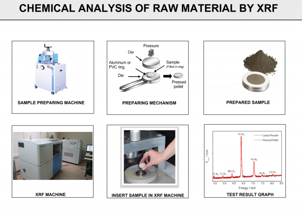
4-1)Chemical Analysis:
Different methods are used in reputable laboratories for the quantitative and qualitative analysis of the compounds and chemical elements of Organic, Inorganic, Metallic powders, and Binders used in the production of welding flux.
These include the use of Xrf – Xrd – Atomic Absorbtion – CS-ON equipment. The following image shows an overview of the XRF application in rutile flour powder analysis( figure E).
FIG E
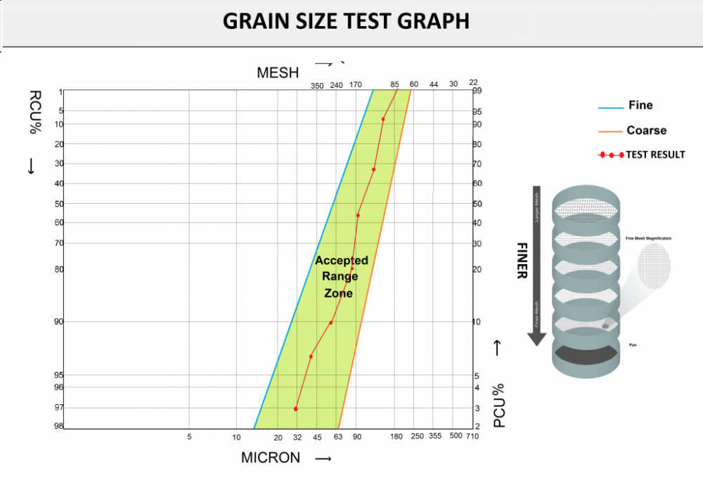
4-2)Grain Size Test (Sieve Analysis):
Different methods are used to control the grain size of the powder. For coarse powders, sieve analysis is used while for fine powders, laser particle size method is common (Figure F). Proper grain size of the raw materials will direct effect in the final welding flux grain size(figure I).The result of this test will insert in a graph like To compare with the approved range.
FIG F
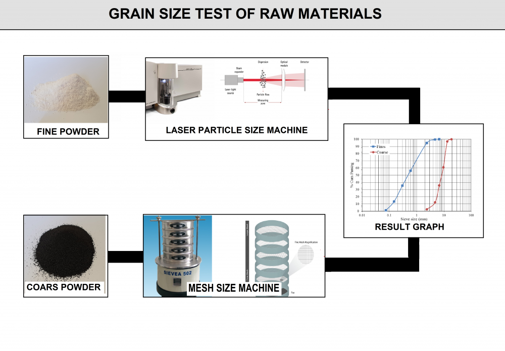
FIG I
4-3)Physico-Chemical Tests:
Other parameters that affect the quality of the raw materials are as follows (it should be checked due to the spec sheet):
.Density &Bulk density
.LOI (loss of ignition)
.ASH
.Humidity or moisture (physical water & chemical water)(figure H)
.Stabilize range (SR)
.Viscosity (figure G)
.Baume
.Molar ratio
One of the important issues in the production of welding flux is LOI. This parameter is used to identify the amount of released gases during welding. If harmful gases produce over the limit, part of the gas will not be able to remove from the weld pool. This will result in gas holes in the weld metal and slag (figure A15).
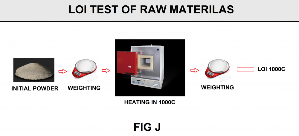
The method of this test is to measure certain amount of powder and then heating at 900 ° C for 2 hours (according to ASTM). After this time the powder will be reweighed. The difference between the primary and secondary weights will indicate the amount of gas phases (Figure J).
FIG H
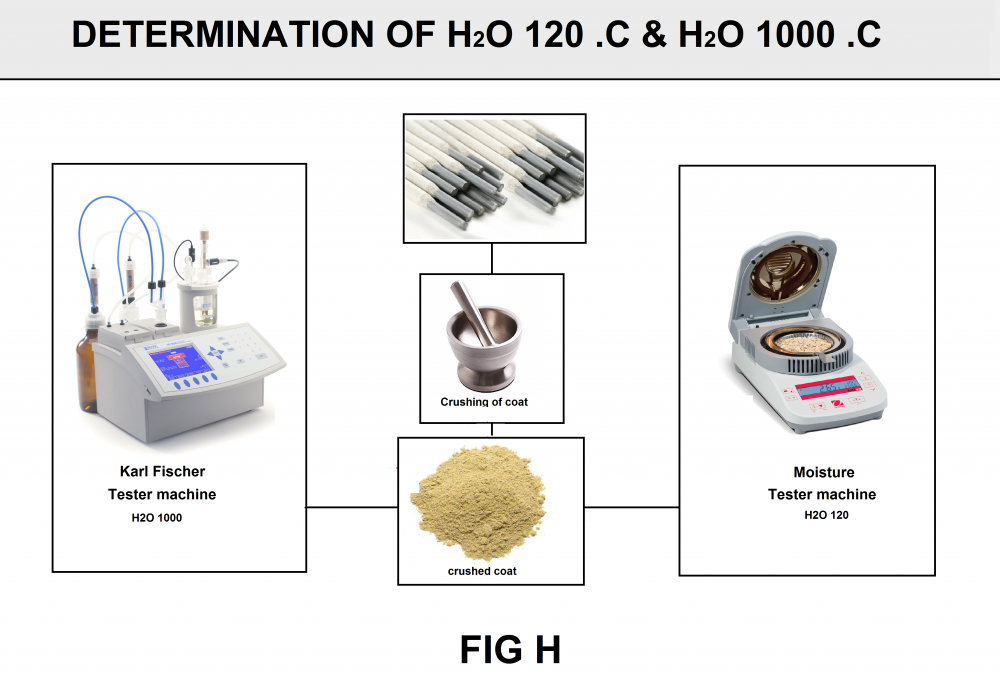
FIG G
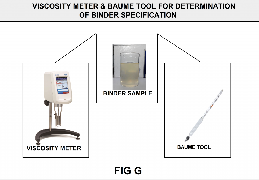
FIG A15
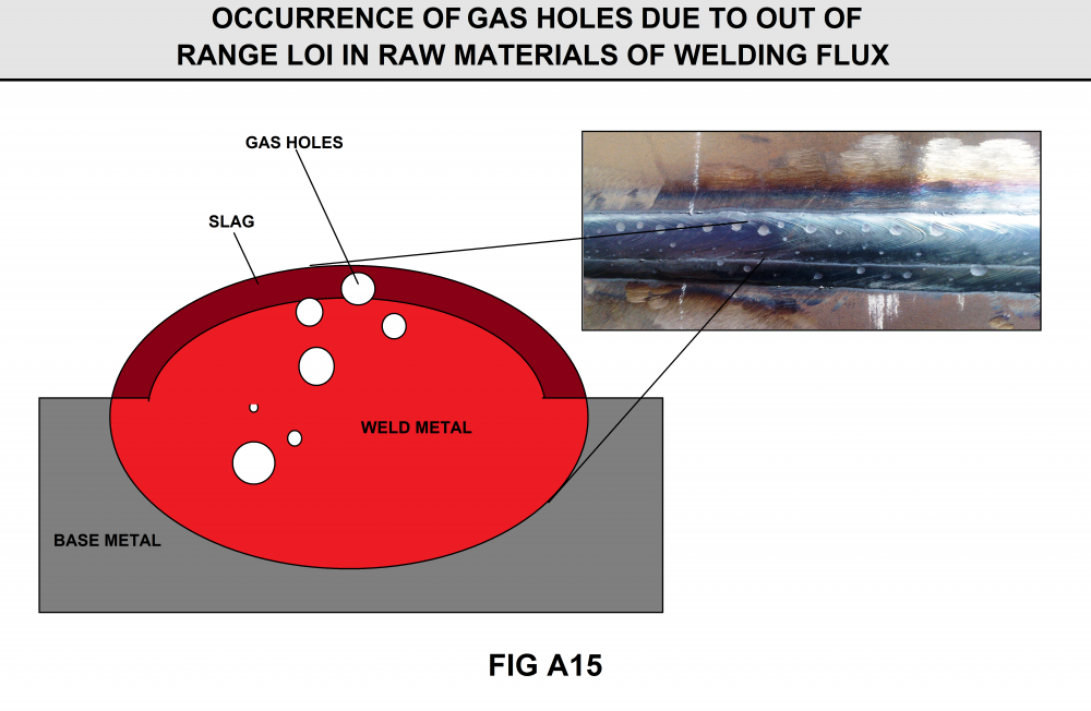
FIG J
5) Manufacturing Of Welding Flux With In-Line Qc :
This section describes the various parts of the agglomerate welding flux manufacturing units and their tasks. Similar to the covered electrode manufacturing process, the quality plan of this process can also be designed and implemented by the WESPEC.
As shown in (Figure A3), each equipment is displayed with a code. The names of these units and their tasks are as follows:
FIG A3
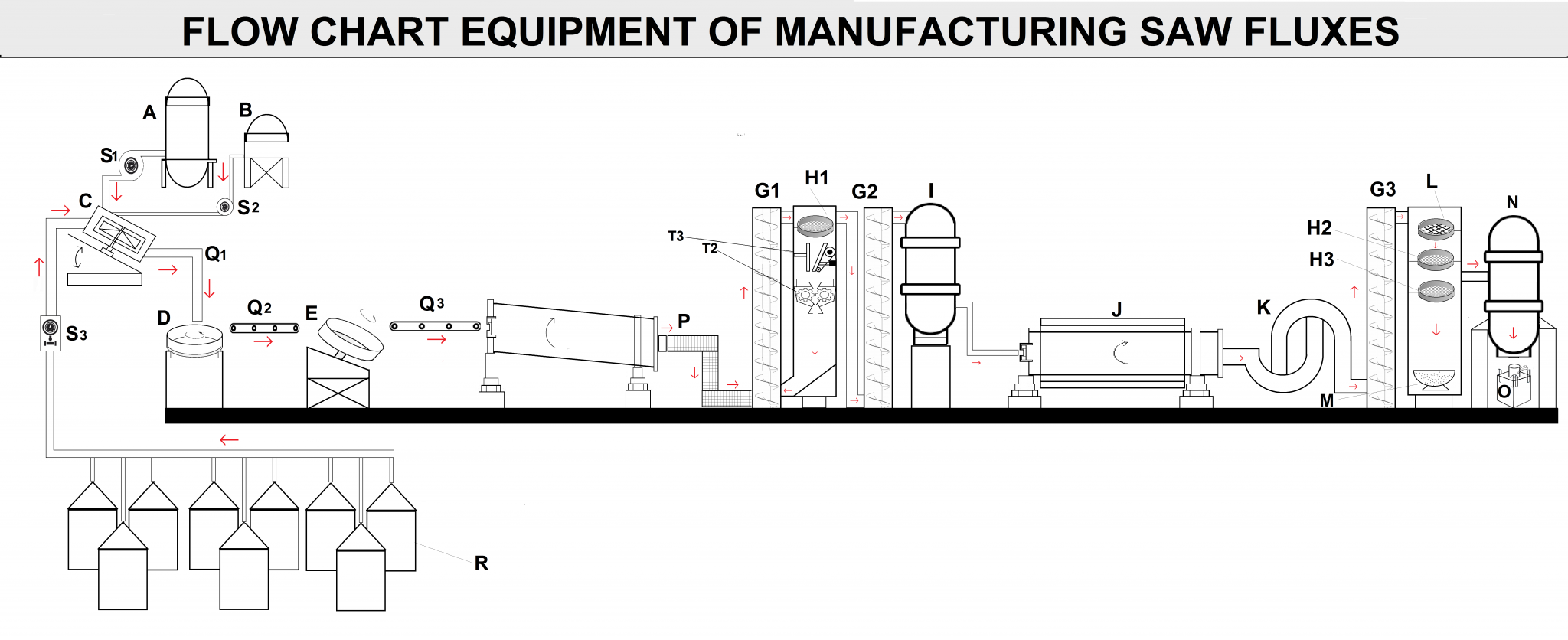
FIG A3
5-1)Entering Raw Materials Into the Mixer:
Raw materials for the production of welding flux include dry powders, binders, and water. According to (Figure A3), dry raw materials are fed into the mixer by the force of suction with PLC system instructions. In the absence of dry powder transfer equipment, it is also possible to manually weigh the raw materials and transfer them to the mixer by manpower.
Required binders are transferred from the storage tanks to the mixer by a fluid transfer system. Similarly, also water has the same process.
Due to priority in charging the material to the mixer, The first one is entering the dry powders to dry mixing step, then by adding water and binder wet mixing would be done.
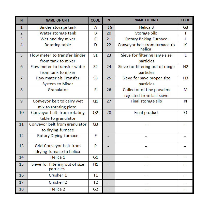
5-2) Mixer (Figure B3 and Code C in the Figure A3):
The mixer is designed to be able to adjust the angle to the surface.This capability is important because after dry mixing and during wet mixing the initial granulation and grain sizing is performing by decreasing or increasing the angle of the mixer.
The next important point is the rotation of the mixer pot in the opposite direction of the mixer blade due to the proper movement of the powders. In addition, a scraper blade is provided to remove the materials from the wall and preventing them to adhesion to the inner body of the mixer.Mixing time, pot angle, speed of the blade and other parameters are according to the instructions and controlled by PLC system.
FIG B3
5-3) Rotating Table (Code D in Figure A3):
This equipment is used for transferring the wet mixed powders from the mixer to the granulator.
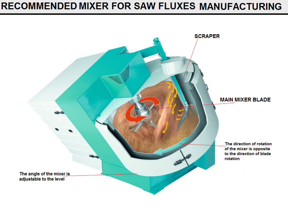
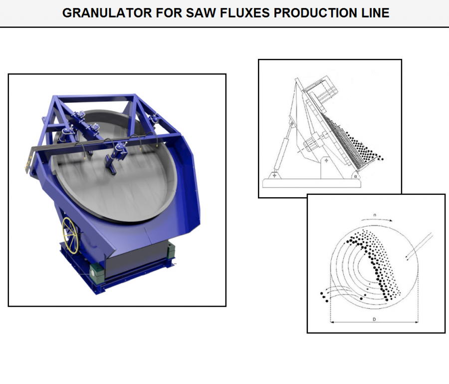
5-4) Granulator (Figure C3 and Code E in Figure A3):
The main task of this equipment is to granulate the powder. Based on the engineering fact, changing the granulator angle can affect the size of the powders. The granulator angle is directly related to the grain size. In addition, the inlet load and rotation speed have also a direct effect on the grain size.
FIG C3
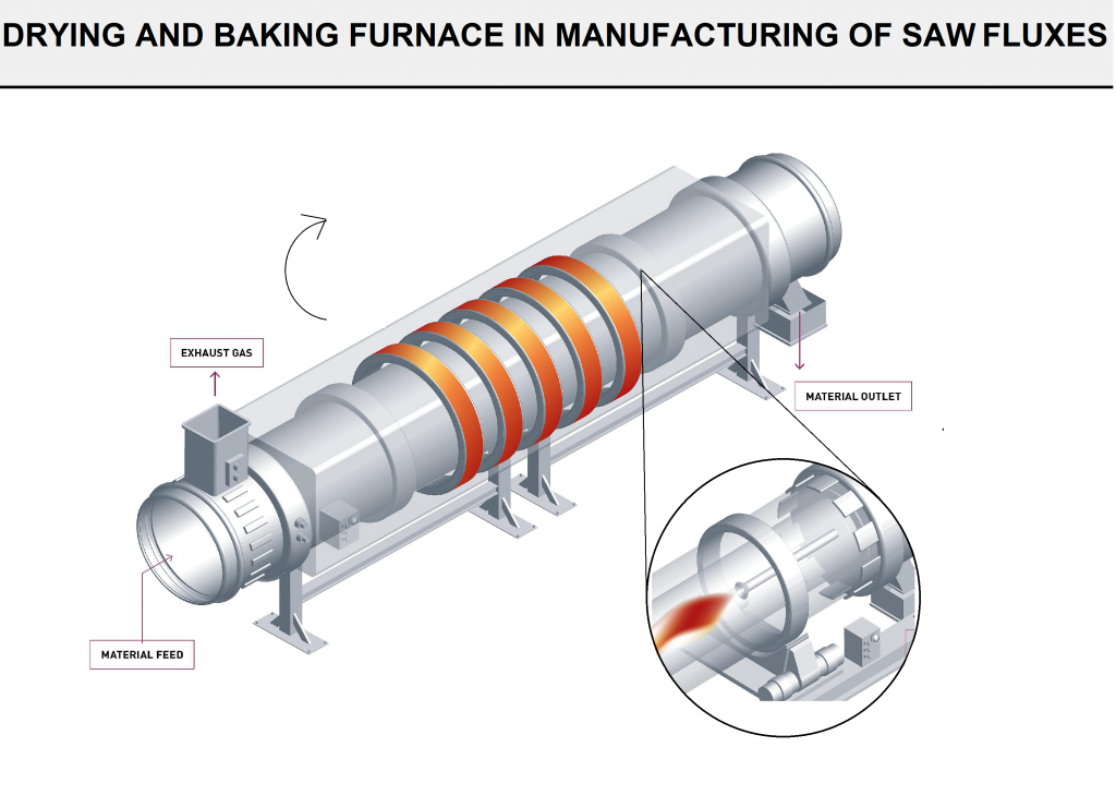
5-5) Rotary Drying Furnace (Figure D3 and Code F in Figure A3):
This equipment is responsible for initial heating and reducing the moisture content of the powder to remove physical water and other volatile compounds at low temperatures. The operating temperature of this equipment is in the range of 80 to 300 C and has a spiral and annular inner surface for powder extraction. The end of the furnace has been designed with special geometry to maintain and transfer flux. The furnace is about 5 to 6 meters in length. This gas furnace is heated by mounted torches in various locations.
FIG D3
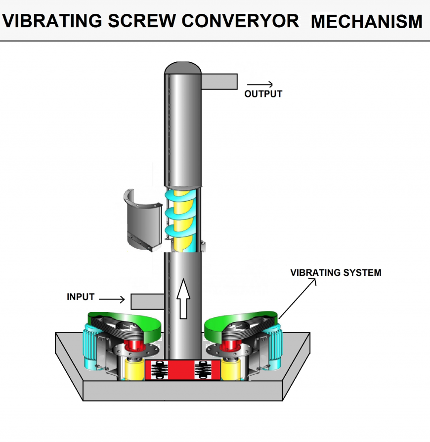
5-6) Helica1 (Vibrating Screw Conveyor)(Figure E3 and Code G1 in Figure A3):
Due to the screw structure inside the helica and the vibration force applied by the two motors, the granulation operation is applied to the powders as well as The transition to the next stage takes longer.
FIG E3
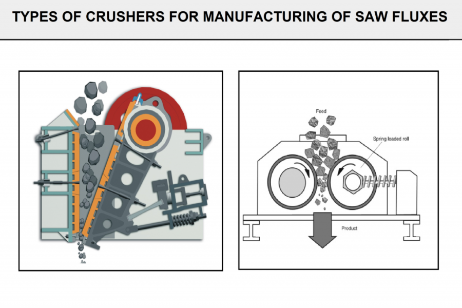
5-7) Sieve1 and crusher1 and 2 (figure F3 and code H1 and T1 and T2 in figure A3 ):
The equipment is adjusted vertically in line. The past powders from sieve 1 are stored directly into the silo and the coarse powders left on the sieve are sent to the crusher 1 and 2 to get the proper size. The crushed powders are resend into helia1 and then poured onto sieve 1 again.
The crusher 1 has a abrasive plate structure, and the crusher 2 is designed as spindle adjustable rollers. According to (figure F3).
FIG F3
5-8) Helica2 (Vibrating Screw Conveyor) (Figure E3 and Code G2 in Figure A3):
Helica 2 is similar to helica 1 in structure and function. This equipment is responsible for transferring flux from sieve 1 to storage silo.
5-9) Storage Silo (Code I in Figure A3):
Before the final baking stage, we need stop condition for the next steps . The benefit of this method is that it is possible to store the flux before entering the final baking. This will allow planning the furnace operation time and subsequent steps.
5-10) Rotating Baking Furnace (Figure D3 and Code J in Figure A3):
The operating temperature of this gas furnace is in the range of 700 to 850 ° C. The structure is similar to a preheating furnace with a spiral wall and heat transferring through the various locations. the end of the furnace has a specific geometry for holding and overflowing it. Another important factor is baking time, according to the baking instruction, the time will be in the range of 45 minutes to 1 hour.
5-11) Conveyor with Vibrating and Cooling System (Code k in Figure A3):
The flux removed from the baking oven will move on the conveyor, while being directed to the final sieve section. This conveyor is equipped with a cool water system to reduce the temperature and has a vibrator system to move the powder to the helica3.
5-12) Helica3 (Vibrating Screw Conveyor)(Figure E3 and Code G3 in Figure A3):
This equipment is responsible for transferring the flux from the conveyor to the final sieve.
5-13) Sieve for Filtering Large Size Particles (Code L in Figure A3):
This sieve has the task of separating the coarse grains in the flux if leftover and adding it to the powders used in the production process at the beginning of the Helica 1 to achieve the desired grain size by crushing them.
5-14) Sieves for Filtering Out of Size Particles & Sieves for Save Proper Size Particles (Codes H2 & H3 in Figure A3):
The fluxes that will transfer to sieve L, will be cross over, but out of range fluxes will be retained on sieve L till re-crushing in stage T2 & T3. The finished product that will transfer to storage silo will be those ingredients that cross over Sieve H2 and remain on the sieve H3.
It should be noted that the size of the sieve 1, 2 and 3 for each product is unique and They will install on the production line.
5-15)Collector of Fine Powders Rejected From Last sieve (code M in Figure A3):
If fine powders pass through sieve 3, They will go to the surface of the fine powders collector. According to the production instruction of each powder, the specific weight of remain fine flux would be added to the final product.
5-16) Final Storage Silo (Code N in FigureA3)
According to the PLC system, The flux in this silo is transported directly into the packing bags.The type of packing can be different depending on the properties of the flux and customer requirements. For example, basic welding flux are sensitive to moisture absorption and require moisture-resistant packaging. Other packing methods can also be used to pack large amounts of flux.
6)QC of Final Welding Flux
welding flux qualification is one of the most important steps in the flux manufacturing plant. At this stage, it is necessary to perform all tests that are defined in the relevant standards, but in some cases regarding customer requirements, we could have simulation, including welding in different conditions.
These tests are as follows:
6-1) Humidity Test:
The moisture content of the flux after the final baking is a very important qualitative parameter. This item is usually mentioned in the specification sheet wich called Physical Water Extracted at 120 ° C and Chemical Water Extracted at 1000 ° C.
6-2) Welding Performance & Visual Test of Weld (VT):
At this stage, to check the quality of the product, welding is performed in different conditions. Visual test is also performed to control the following items:
.Shape of beads
.Penetration rate
.Convexity and concavity of weld beads
.Slag detachability
.Checking the possible defects like porosity, undercut, crack, spatter, worm holes, etc.
6-3) Destructive and Non-Destructive Tests & Chemical & Microstructural Tests:
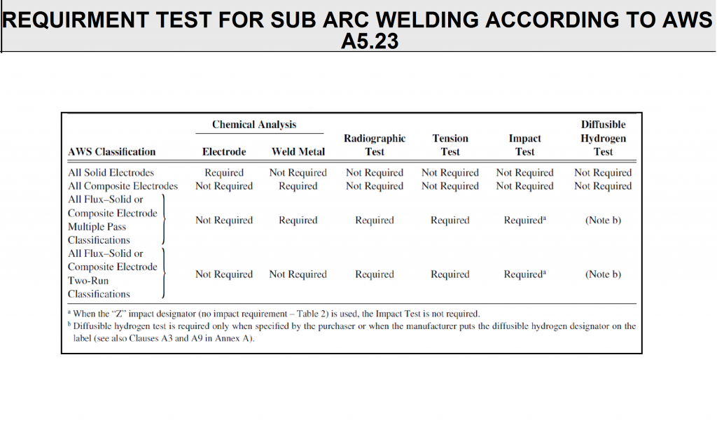
each welding flux has its own quality parameters defined in its own standard. For example, for the F7A2-EM12K wire and powder, these parameters are defined in AWS A5.23 (figure J3).
FIG J3
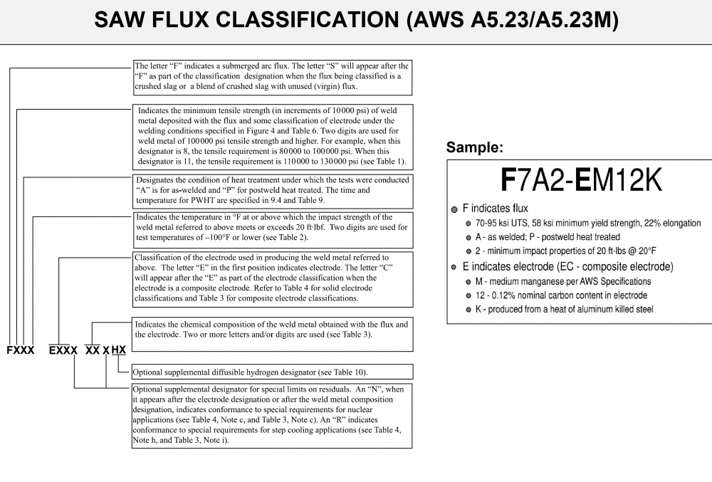
The standard also provides precise definitions of the required tests and how they are performed (figure K3).
FIG K3
These tests include:
6-3-1) Destructive Test of Weld Metal:
.Tensile test
.Impact test
.Hardness test
.Bend test
.Wear test
.Fatigue test
.CTOD
.Hydrogen test
6-3-2) Non Destructive Test of Weld Metal:
.VT
.PT
.MT
.UT
.RT
6-3-3) Chemical Analysis and Phase Analysis of Weld Metal:
.XRF
.XRD
.CS
.Atomic Absorption
.ON (Oxygen & Nitrogen Detector)
.Spectrophotometry
6-3-4) Microstructural Study Tests:
.Microstructural study with light microscope
.Microstructural study with SEM
.Microstructural study with TEM
6-3-5) Corrosion and Erosion Tests According to Need:
The number of these tests is very high and only requires those that are defined by the relevant standard or are able to pass these tests as required by the customer.
There are many tests to determine the corrosion and erosion resistance of weld metal. It is important to note that the tests defined in the standards need to be performed.
6-4) Tests for Welding Flux Qualification:
6-4-1)Density test of flux
6-4-2)Grain size test of flux
6-4-3)Basicity index
6-4-1)Basicity index
Basicity is commonly used to describe the metallurgical behavior of welding flux. The basicity index is a ratio between basic and acid compounds (oxides and fluorides) of which the flux is composed.
There are several ways of calculating basicity and in welding Boniszewski’s formula has become the predominant way of calculating basicity.
Welding fluxes can be divided into three groups:
| Type of welding flux | Basicity |
| Acid fluxes | <0.9 |
| Neutral fluxes | 0.9 – 1.2 |
| Basic fluxes | >1.2 |
Basicity has a great influence on the impact toughness of the weld metal. Increasing basicity brings down the oxygen content and hence the inclusion level in the weld metal. Consequently, the impact toughness will increase and also, to a limited extent, the ductility of the weld metal.
The relation between basicity and impact toughness is particularly important for high alloyed grades, such as duplex steels.
Perhaps the most convenient method of classifying, however, is by reference to the ‘basicity index’ (BI) of the flux. The index is calculated by dividing the sum of the percentages of the basic constituents by the sum of the acid constituents. Calcium, magnesium, sodium, potassium and manganese oxides, calcium carbonate, and calcium fluoride are the basic constituents of a flux; silica and alumina the acid constituents.
At the final stage of the quality control plan for welding flux, the results of the tests are recorded in the final specification sheet of manufactured powder (figure L3) and compared with the SPEC sheet.
Sometimes, depending on customer requirements, Tests are defined that simulate the service conditions of the welded parts.
A manufacturing company does not need to supply all of these equipment, it can outsource them to laboratories for quality certification.
The frequency of sampling, reporting and refining the results of these tests in the implementation of the quality management system will be fully performed by the WESPEC .
FIG L3