Wire Drawing Dies
Wire Drawing Dies are One of the most important technical issues in the drawing process. the proper choice of drawing dies and lubricants is very effective in the final quality product. We will focus on types of wire drawing dies.
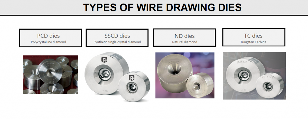
The wire drawing process reduces the size of a ferrous or non-ferrous rod down to a variety of finished sizes including super fine wire. This process is accomplished by passing the wire or wires through a series of single or multi-wire drawing machines. The drawing dies used in these machines can be Tungsten carbide, Natural Diamond or Synthetic Diamond, and the type of die utilized is choosen by the type of material being drawn. These tools are constantly under the high temperature condition because of wear between wire and dies (Fig D4).
FIG D4

Before studying the types of dozes, you can read the main geometric specifications of dozes in This Article.
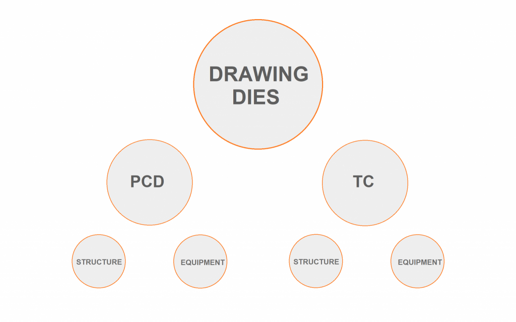
Classification of Wire Drawing Dies
Based on wire material, the classification of dies are(FIG C4)
FIG C4
Cemented carbide:
Tungsten carbide (WC)
Diamond: single crystal natural (SCN):
single crystal synthetic(SCS)
polycrystalline(PCD)
Ceramic:
titanium carbide(TIC)
titanium nitride(TIN)
cubic boron nitride(CBN)
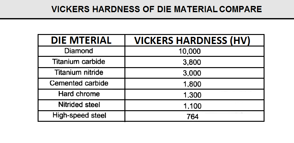
The important properties of wire Drawing dies are:
Wear resistance
Toughness
Modulus of elasticity
Thermal conductivity
Coefficient of friction
Table below compare the hardness between different material(FIG F4)
FIG F4
Properties And Characteristic Of Wire Drawing Dies Types:
The following sections cover the properties and characteristics of different types of dies
Tungsten Carbide Dies:
is a hard cemented carbide composite made from tungsten carbide powder and a suitable binder material. Such as cobalt. The most common tungsten carbide nibs are made from medium grain size tungsten carbide powder with 6-13% cobalt binder.
The most advantages of tungsten carbide nibs are toughness and resistance to fracture, which depend on the tungsten powder grain size and amount of cobalt used .higher cobalt binder content results in more ductile die material with lower hardness and wear resistance . these dies are used to draw larger diameter wires with heavy reduction at slower speed without much loss in die life.
tantalum additions Improve crater resistance and decrease galling damage and die scratching. Die with tantalum addition are used to draw stainless steel, aluminum alloys, galvanized wire. Titanium additions increase hardness, improve abrasion resistance, and lower density, but brittleness is increased.
Sub micron tungsten grade containing titanium give increased die life when drawing fine high carbon steel wire like tire cord. These alloying additions delay the point at which craters on the die surface make the die unfit for further use. When selecting a tungsten carbide grade, it is always desirable to use the hardest grade with lowest binder content and finest grain size possible without encountering die package. this will give maximum die life .
for any given application, there is usually one combination of grain size and binder content that would be the optimum. However, to supply dies for each individual application, carbide producers would have to have hundreds of grades available. Since this is impossible, producers have selected the most popular compositions as standards. Table below shows cobalt content and tungsten carbide grain size for the most common grades used for wire through bar drawing applications(FIG H4).
Tungsten Carbide dies are the foremost choice in drawing equipment of wire-industry when an economical option is desired over better wear resistance and wire-surface finish. Tungsten Carbide dies are little, ultra-hard precision tool with a small hole at its center.
A tungsten carbide die is normally purchased as a rough cored die, which requires the die to be ground and polished to prepare it for wiredrawing. If finished dies are purchased from a die supplier, they are usually returned to the supplier when they become worn. The used dies must then be cleaned, inspected, and if badly worn, recut to a larger diameter before reuse in a drawing machine.
Tungsten carbide is almost three times harder compared with steel and it is of high density than titanium. What this means for companies who use dies is that a tungsten carbide die has a superior wear resistance when compared to dies made out of other materials. When dies last longer that is equal to a reduced cost of money in not having the cost of replacing them and in reduced downtime for machinery waiting for new dies to be installed.
Tungsten carbide has a hardness between 85HRA and 92HRA. Diamond has a hardness rating of 10, however, diamonds aren’t as versatile and are obviously a very expensive die material. In particular, it has the highest hardness and thermal conductivity of any bulk material. Those properties determine the major industrial applications of diamond in cutting and polishing tools.
Diamond Dies:
is carbon with special cubic crystalline structure.it is the hardest of all die materials. Natural diamond also has the best heat conductivity. three types of diamond are used for wire drawing dies:
–SCN: single crystal natural
–SCS: single crystal synthetic
–PCD:polycrystalline diamond
SCN Dies:
since it is a single crystal. It can be polish to very smooth finish with very low friction.Hardness and coefficient of friction of single crystal natural diamond dies vary with crystallographic orientation and results in increased die wear along certain crystallographic directions. Toughness is very poor for natural diamond as the diamond crystal has naturally weak points called cleavage planes where fracture occur easily .single crystal diamonds produce the ultimate surface finish and are used for final dies where a bright clean surface is required.
SCS Dies:
it is manufactured synthetically, but the arrangement of carbon atoms in the single crystal is the same as in natural diamonds. Synthetic diamond gives more uniform die wear than single crystal natural diamond dies .SCS dies have slightly less abrasion resistance and slightly less fracture toughness than natural diamond. Thermal conductivity is 2-3 times better than natural diamonds die, which would be advantageous in high speed drawing where heat generated is higher and cause rapid die wear, poor wire quality , and lubricant break down. Natural diamond and synthetic single crystal dies are generally used to draw small diameters in wet wire drawing machines.
PCD Dies:
Pcd blanks are currently produced in self-supported or tungsten carbide supported blanks that are more often used in ferrous wire drawing applications.
Self-supported blanks are generally offered in two grain sizes ( ≤1-5 micron) and two grades ( thermally stable catalyst metal removed-TS , and metal filled ,contains catalyst metal-MF). Tungsten carbide supported blanks have a core integrally bonded to a tungsten carbide supported ring. these blanks are generally offered in fourteen sizes and four grain size( 3-5-25-50n microns).
Polycrystalline diamonds are characterized based on grain size, usually in four categories : coarse , medium , fine , ultra-fine. Grain size is difficult to classify because each manufacturer rates grain size differently. There are certain performance trends related to grain size as summarized in (FIGJ4).
Grade selection should be discussed with the die supplier to ensure the best technical approach for specific wire drawing applications. Keep in mind that diamond blanks have limited height, therefore , approach angle and bearing length my need to be compromised to ensure the wire contacts the correct location within the blank for a given reduction. Generally , wider angles and short bearings are used in PCD dies. Figure K4 shows the application of different types of PCD dies.
Die suppliers use a number of method to mount PCD die blanks into a suitable casing. Figure L4 shows the typical mounting method for a supported blank.
Diamond Die Specification
Diamond dies are used on wet drawing machines when extreme ly close diameter tolerance or high surface finish is required , and for steel wire (0.18mm) and smaller . die pressure when drawing fine wire is relatively low and diamond die breakage is not likely.
Diamond dies are used for wire sizes from (0.18-0.76 mm) at higher drawing speeds where thermal conductivity is important. polycrystalline diamond is replacing tungsten carbide and natural diamond in many applications, in which the following parameters are desired:
-increased wiredrawing machine speed
-better size tolerance
-more consistent wire quality
-better cost efficiency
Specifications for single crystal and polycrystalline diamond dies for drawing various metals are listed in (FIGM4).
Generally dry wire drawing process is used more so in the drawing of steels and bigger sizes of wires. In case of copper, aluminum and their alloys, generally wet wire drawing are used.
Design Of Wire Drawing Dies:
As it has been illustrated on this picture (FIG G4),a die-in general condition has geometrical structure, in addition, the development of technology in this specific industry has many effects. However, this is geometrical standard for all dies which dependent on this method.
FIG G4
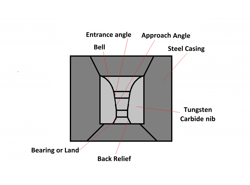
Steel Case:
The casing should be made of good quality steel with a hardness of 20 to 25 Rock-well c. The outside diameter should be concentric with the inside bore and square with the face to produce consistent die geometry. The inside bore should be precision machined to a close tolerance to ensure a correct press fit with the carbide nib. Without the proper press fit , higher tensile material can crack the nib causing a catastrophic failure of the die.
Bell Radius:
The bell radius incoming rod entering a wire drawing die on a spiral path, such as paying off into a bull block or ripper die. As rod or wire should enter a die as straight as possible to prevent uneven stress on the material. It should contact this surface only for a moment before becoming centered into the approach zone. The bell can be left rough cord as supplied by die manufacturers, and any polishing of the bell is only for cosmetic appearance because no drawing should ever take place here.
Entrance Angle:
The function of the entrance angle is to direct the flow of lubricant into the working zone of a die. As with the bell radius, it can be left unpolished. the normal entrance angle is a 40 degree included angle in standard R5 series wire dies.
Approach Zone:
The approach zone is the most important section of a wire drawing dies. Reduction in area and lubrication of the incoming wire surface occur here. The efficiency of any die is determined by the design and accuracy of this approach zone, which must be cut to an accurate conical angle with a smooth surface finish . sides of the approach zone must be straight without a distinct radius or blended contour along its entire surface . the angle must be precision-machined to ensure the angle and die surface have a common centerline. in addition , these surface must be concentric with the outside diameter of the steel case to prevent out-of-round wire . the normal angle used in wiredrawing are usually between 8-20 degree included angle .
Bearing:
The function of the bearing is to control the final diameter of the drawn wire, guarantee its roundness and straightness, and produce a flat, smooth surface finish. For these reasons, the round , parallel surface must be machined to a close dimensional tolerance to produce quality wire . length of the parallel bearing surface should be form 25-50 % of the diameter to prevent the die from rapidly wearing oversize .the bearing length selected depends on hardness of the drawn wire and desired lubricant film .typically , harder materials use shorter bearing lengths, such as 25% or 35% , to prevent heat buildup that can cause lubrication failure . softer materials can use bearing lengths of up to 50%, which maintain final wire size for a longer time. Retaining the die size allows the wear ring to be removed without shortening its length, which usually requires removal from service . however , longer bearing length create more frictional heat that can burn lubricant.in slow speed drawing applications ,long bearings have been used to generate heat to melt lubricant on the wire surface that is needed for secondary fabricating operations. Bearing lengths are described as short 20%, medium (30-50%) and long ( 75%). The majority of wire drawn in the united states uses medium bearing length dies.
Back Relief:
the back relief is a conical angle designed to strengthen the exit of the wire drawing dies and prevent nib breakage. it also keeps the metal forming area centered in the nib since its length positions the bearing and approach angle higher in the nib . the back relief angle is usually preformed in a rough cord die with an included angle from 30 to 90 degrees.
Meeting Point in Wire Drawing Dies
As Described Drawing Dies include the seven main parts:
- Tungsten carbide nib
- Steel case
- Bell radius
- Entrance angle
- Approach zone
- Bearing
- Back relief
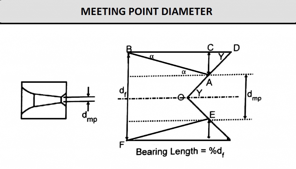
The meeting point diameter is where the approach angle meets the back relief angle before the final diameter and bearing are machined in the die. The approach angle generally is machined in an internal die grinder with a diamond pin to enlarge the angle to the desired meeting point diameter. Meeting point diameter is a function of the approach angle, the bearing length, as a percent of the final diameter, and the back relief angle.
(FigA11) shows the meeting point diameter location in a drawing die nib and the geometry involved in calculating the correct size for a given approach angle bearing length and back relief angle. When finishing the die shown in this figure, the distance (CD) must be removed to form the correct bearing length (BD) and final diameter.
Meeting point diameter (dmp) is usually expressed as a fraction (X) of the final diameter (df ). Consider the geometry shown in (FigA11):
- Included approach angle =2α
- Back relief angle =2∂
- Meeting point diameter =Xdf
- Bearing length =%df
By using these parameters, the fraction X can be calculated as a function of the approach semi-angle (α), half of the back relief angle (∂), and the bearing length (%df), as shown in Eq1
Values of the fraction X may be calculated by using a computer program or summarized in a meeting point chart to assist the operator in determining the correct meeting point diameter for a particular die specification. (FigB11) gives the fractions calculated for several included approach angles ( 2α= 8 degree, 10 degree, 12 degree, 14 degree, 16 degree, 18 degree, and 20 degree) and bearing lengths (25%, 35%, 50%, and 66%) for a specific back relief angle ( 2∂ = 90 degree).
How is this meeting point chart used? Consider that one wants to make a die having the following specifications:
- Included approach angle,2α = 12 degree
- Back relief angle,2∂ = 90 degree
- Final diameter,df = 0.125 in. (3.175 mm)
- Bearing length = 50%
First locate the 12 degree column on the left of the chart. Then locate the 50% bearing column and find the fraction that corresponds with these two parameters. The fraction is 0.9049; therefore, the meeting point diameter is 0.9049 x 0.125 or 0.1131 in. (2.873 mm).
Note: If the back relief angle changes from 90 degree, a different fraction must be calculated by using Eq1.
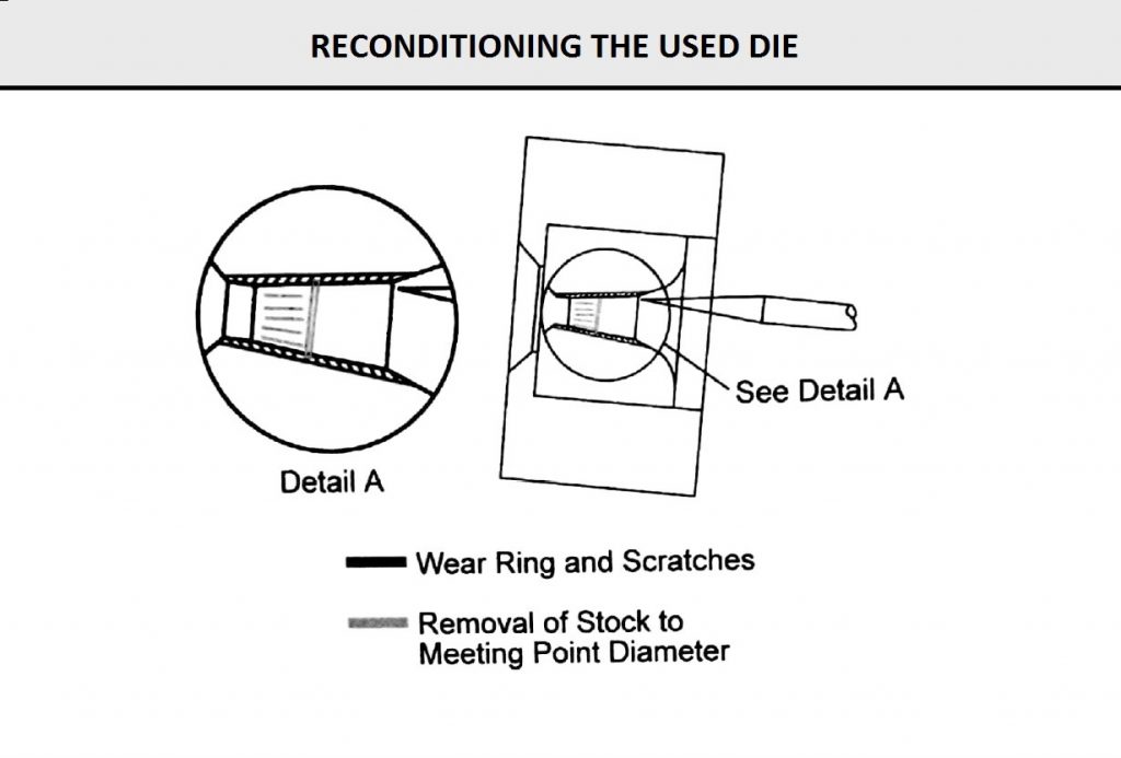
(FigC11) shows how wear ring and scratches in the approach zone of a used die are removed. The shaded area is this figure is machined away to the meeting point diameter of the new die size.
Fig A11
Eq1

Fig B11
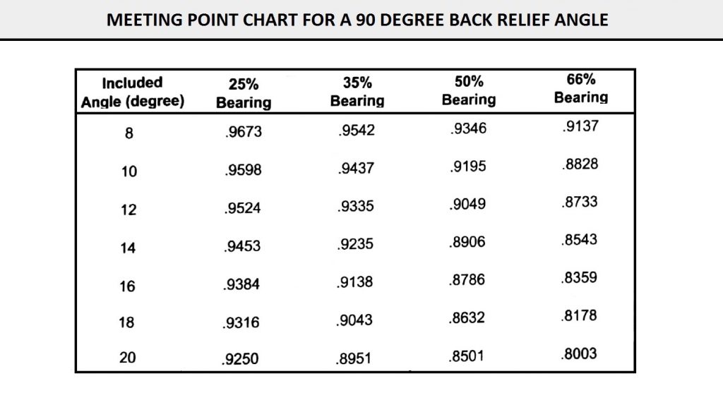
FIG C11
Equipment and Finishing Process for Wire Drawing Dies
Finishing Process
The normal die finishing process is a three-step procedure: (1) grind the approach to the meeting point diameter; (2) polish the approach surface to remove grinding marks and generate a highly polished surface; (3) lap/size the bearing diameter from the meeting point diameter to establish the specified final diameter and bearing length.
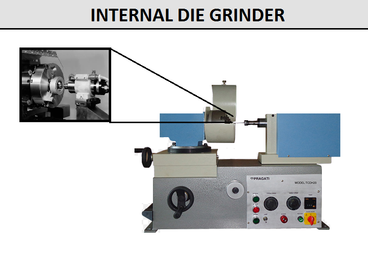
Step 1: Grinding the Approach Angle
An internal die grinder is used for this first step (see FigD11). The die is mounted in a work-holding chuck or collet and is checked to ensure that the die is mounted correctly and is held concentrically in the holding device. The grinding operation uses a 12 degree electroplated diamond cutting pin offset at the tailstock housing to a 6 degree angle causing the back side of the pin to be parallel to the centerline of the machine. The die is then swiveled to its half angle at the headstock housing holding the die. Some grinders use different degree pins for different angles.
Figure shows the set up for a 12 degree approach angle using the offset pin. The die rotates in the opposite direction of the pin. The pin rotates very rapidly and moves back and forth to generate a better surface finish on the die. The grinding machine feeds the die into the pin automatically to create cutting pressure.
The centerline of the approach angle coincides with the centerline of the die case when the approach angle is finished this way. Using a single layer of diamond abrasive affixed to the outer surface of the cutting pin assures an accurate approach angle. The cutting pin is replaced when it fails or loses the ability to cut properly; however, the shape of the pin is not changed, so the accuracy of the angle is not lost.
Different diamond grit sizes can be used on the cutting pin to obtain the desired surface finish. Since the pin has a single layer of diamond abrasive affixed to its surface, little if any diamond grit becomes embedded into the carbide surface. This finishing method also leaves an extremely flat and consistent surface finish in the surface of the die.
FIG D11
Step 2: Polishing the Approach Angle
Modern die polishing machines employ the same 6 degree offset angle and hardened steel pin with a 12 degree conical angle (see Figure F11). Some machines use steel pins having different angles. The headstock holding the die is swiveled to the half angle for setting the approach angle. Diamond paste provides the cutting action, and it is applied to the pin surface, which is placed inside the approach zone making contact parallel to the die surface. The pin and die rotate in opposite directions, with the pin moving in a stroking motion to generate a better surface finish in the die. Spring tension holds the die against the pin and an electric timer controls the finishing time. The normal cycle time is four minutes, which includes the operation to remove grinding marks to improve approach zone surface finish in the die.
Step 3: Lapping the Bearing
Lapping the bearing requires a cylindrical steel pin with a diameter larger than the starting diameter of the die. The lead end of the pin is ground into a small taper to permit it to enter the die, and diamond paste is applied to this lead area. The pin is fed into the die making 360 degree contact. The die sizing machine has a touch screen selection program for setting travel distance, contact touch, pressure, finish stroke rotations, and automatic cycle stop (see Figure G11).
For small diameter dies, e.g., under 0.025 in. (0.64 mm), non-contact lapping is employed when the lap is not rigid and could bend when lap contact is made with the die. This non-contact lapping method employs a lap slightly smaller than the meeting point diameter of the die. The lap is fed into the die and rotated to initiate cutting action. In this lapping method, the lap never contacts the die; only the diamond abrasive paste between the lap and meeting point of the die makes direct contact. This lapping method works well for small diameter dies where diameter increase is small.
F11&G11

Grinding the Bearing
Grinding the bearing is identical to grinding the approach angle except the die is swiveled to a zero position that is parallel to the centerline of the machine (see Figure D11). This aligns the bearing on the same centerline as the approach zone and die case. Bearing grinding is generally used for larger diameter dies that have a large difference between meeting point and finish bearing diameter. This grinding method produces a very accurate, parallel, and round bearing having a sharp intersection between the bearing and approach zones with no tapering or blending (see Figure H11). After grinding, the die is normally polished on the die-sizing center using the steel pin and a non-contact method with fine diamond paste. The die must be ground smaller than the finish diameter to leave enough material for the polishing step.
Polishing on Grinder
The development of fine, super-abrasive polishing pins in grit sizes from 600 to 1600 have led to finish grinding die surfaces without the need for loose diamond abrasive. This polishing method-employed on the internal die grinder-will achieve the smoothest and most consistent finish with surface finishes below 1 RA* see (Figure I11). Grinder polishing has advantages for finishing larger diameter dies; however, diameters smaller than approximately 0.060 in. (1.52 mm) are difficult to achieve due to the sharp point required on the pin. A
Spray mist system is also required to wet the pin with water. Dry grinding cannot be used with a polish pin since pin damage will occur from heat generation and loose abrasive on the pin surface.
If these finishing steps are followed and modern die finishing equipment is used, manufacture of dies will be more accurate and productivity will increase when these dies are used in wiredrawing machines.
To produce quality dies, the following physical characteristics must be achieved:
For Approach Zone
- Accurate conical angle with a smooth, flat surface finish.
- Straight sides without any distinct radius or blended contour.
- Common centerline with bearing.
- Concentric with the outside diameter of the steel casing.
For Bearing Zone
- Length of the parallel bearing surface should be 25-50% of the bearing diameter.
- Surface finish should be smooth and flat.
- Surface should be parallel over the entire length.
- The area should be concentric with the outside diameter of the steel casing.
Most modern die finishing equipment finishes dies automatically and eliminates costly and inaccurate hand finishing methods. Now, because of this modern equipment, conical approach angles, bearing lengths, parallel bearing diameters, and die concentricity can be held to extremely close tolerances. These dies perform better, give longer life, improve wire output, shorten machine downtime, and lower labor costs.
FIG H11&I11

Other finishing Equipment for Wire Drawing Dies
Die Cleaning
Much production time is lost when operators are forced to clean wiredrawing dies by hand. These dies, in most cases, have heavy lubricant build-up on the steel casing and inside the die. The best method is to employ a die cleaning unit to clean the dies without direct labor. Cleaning machines handle about 25 to 50 dies depending on the die diameter size. Dies are loaded into a round steel drum via the door in the drum. About a third of the drum is sub merged in cleaning solvent, and small holes in the drum allow solvent to enter the drum. Small, shaped ceramic abrasive media inside the drum scrape away lubricant on the die and remove any rust on the die case. The solvent softens the lubricant while the abrasive ceramic media in the rotating drum clean and polish the die case. The normal duration of a cleaning cycle is 20-30 minutes per batch of dies. The solvent leaves a light oil film on the die, which prevents oxidation (rusting) of the steel casing when the die comes in contact with the air. Shelf life of the lightly oiled dies is more than one month without any visible rusting. Ultrasonic cleaning and degreasing units are also available for many die-cleaning applications.
Pin Grinder
Loose abrasive on steel angle pins is used to polish dies, as these pins wear on the conical surface that contacts the die. Normal life of hardened steel pins is approximately 25 dies polished from the grinding step before the pin must be reground to restore the conical angle. A pin grinder is used for this function. steel pin is held in a spring collet, and the same angle size is set on the headstock housing as used in the polishing machine that uses the pin. This keeps the angle size equal in both machines and ensures consistent accuracy in the approach angle. The pin is moved back and forth across an abrasive wheel to cut the proper conical angel. Normally, about 0.002 in. (0.05 mm) is ground from a worn pin requiring between 1 to 2 minutes of grinding.
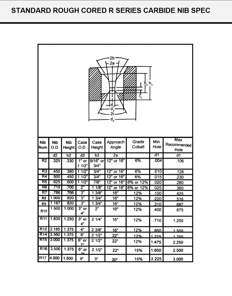
Standard R Series Carbide Nibs
(FigJ11) shows standard rough cored R series carbide nib dimensions and chemical compositions. The minimum hole size and maximum recommended hole diameter is given for drawing ferrous wire under normal drawing conditions.
FIGJ11
Polycrystalline Diamond Die(PCD)
Polycrystalline diamond (PCD)is a synthetic material invented by two Swedish researchers in 1953.Available as platelets (blank) from the years 1974, this material is made from non-oriented diamond crystals linked together. The synthetic mass is sintered in presses at very high pressures and temperatures, in the presence of a bonding metal catalyst.PCD combines hardness, abrasion resistance, strength, toughness and high thermal conductivity. These properties and unique features make it a perfectly tailored and high-performance material in the drawing of numerous materials. It is also suitable for many other applications, combining precision and resistance to wear.
Structure
1) Ordinary PCD Die:
Ordinary PCD die is mostly applicable to draw low carbon steel wires (iron wires) and the performance-price ratio is very high, for example, Gabarro SA (Spanish company) drawn around 300 tons of low carbon steel wire using our one die (ordinary PCD die with hole diameter 3.4mm). Draw low carbon steel wires, ordinary PCD die is the first choice compare with other PCD dies and tungsten carbide dies.
Features:
● Good wear resistance
● Good surface finish
● High machine efficiency
● Repeatability
● Low cost
● Hole diameters: 0.201 – 9.00 mm
2) CD Die Blank PCD Die:
CD die blank PCD die is mostly used to draw copper, aluminium and stainless steel wires with high quality, its accuracy and highly polished finish are almost same as Compax die blank, only wear resistance is around 90% of Compax die blank, CD blank PCD die is a kind of die with high performance-price ratio to draw high quality copper, aluminium and stainless steel wires.
Features:
● Longer die life
● High wear resistance
● High surface finish
● Accurately sized
● High machine efficiency
● Repeatability
● High wire surface quality
● Hole diameters: 0.100 – 9.00 mm
Equipment and Finishing Process
Polycrystalline Diamond Wire Drawing Dies (PCD) Equipment
Finished PCD dies are usually purchased from a die supplier and returned to the die supplier for re-cutting to a larger diameter. Normally, the maximum diameter is dependent on the nib size used. If a wire mill maintains PCD dies in house, two basic machines are used-an ultrasonic die working machine and a wire-polishing machine.
Ultrasonic Die-Polishing Machine
An Ultrasonic Wire Drawing dies shaper is used to shape the reduction, entrance, and exit angles of a die see (Figure K12). Ultrasonic transmission vibrations, a diamond powder mixture, and a shaped needle remove wear damage and reshape the die angles. Finer diamond powders are used to improve the finish on the diamond surface. A die-shaping machine is not recommended for working on the cylindrical bearing surface; this operation is normally done on a wire-shaping and -polishing machine.
FIGK12

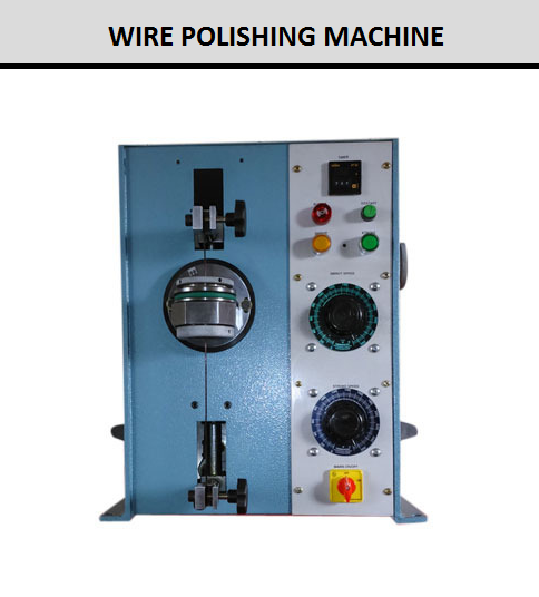
Wire-Polishing Machine
A wire-polishing machine uses diamond powder acting on the die surface through the combined die rotation and translation motions of the die or wire see (Figure L12). The machine normally operates on a timed cycle or stroke counting device. When the PCD bearing diameter is polished or re-sized to a larger diameter, stainless steel wire is drawn through the bearing. The wire is held tightly on each side of the die, and diamond powder paste is added to produce cutting action. This procedure is repeated until the bearing is finished. These machines can also be used to polish and to blend the entrance, reduction, and exit angles of the die. The angular polishing is done by indexing the die off-center and causing the wire to follow die contour. The die angle may not be very accurate by using this method.
FIG L12
Measuring and Gauging
Measuring and gauging equipment must be used to monitor a die during the finishing process in the die shop to ensure accuracy of the inside contour of a wiredrawing die. Other equipment, purchased from outside suppliers or from internal die shops, should be used for quality control of dies that are going into wiredrawing production. The gauging tools that are used in die shops to monitor wiredrawing dies through the finishing steps are described below.
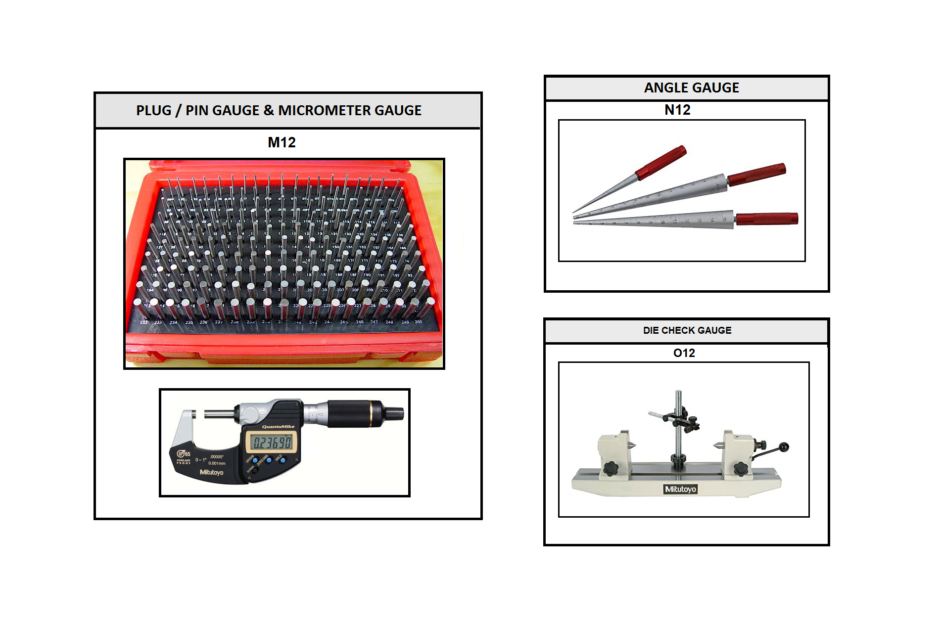
Measurements in the die shop are made by using a quality digital micrometer that is regularly certified see (Figure M12). The micrometer should have a large LCD readout and a resolution of 0.00005 in. (0.001mm) and accuracy at 68°F (20°C) of ±0.0001 in. (0.0025 mm), as well as a friction thimble for a constant measuring force.
The plug/pin gauges are cylindrical steel pins made from 52100 tool-steel having 60-62 Rockwell C hardness and 10 micro-inch finish or better on the gauge surface (Figure M12). The gauges are used during the finishing operations to measure the inside diameter of the dies through a Go and No/Go gauging procedure. To use a No/Go functional check, try to fit both the Go and No/Go gauge into a die. The die will pass if the Go gauge fits and the No/Go gauge does not. A Go-No/Go check is strictly a pass/fail test. The actual diameter size is never measured. Standard gauge sets are manufactured in both English and metric units.
The normal practice to determine gauge tolerance is to allow 10% of the die tolerance to be divided between the Go and No/Go gauges. A Go plug gauge is normally a plus tolerance, and the No/Go gauge is a minus tolerance. By using this practice as a guideline, gauge tolerance is always included in the part tolerance and will account for up to 10%. This means that potentially 10% of good product could fail inspection, but that no bad product would ever pass.
Gauges should be calibrated periodically to ensure accuracy, Gauges, and Go gauges in particular, will wear with normal use and require recalibration. Plug gauges are normally supplied in two class-es-ZZ or X class. The ZZ class, which is used to measure wire dies, have 0.0002 in. (0.0050mm) tolerance and can be ordered in minus gauge size. The X class tolerance is 0.000040 in. (0.0010 mm) and also supplied in plus or minus gauge sizes. The gauges should be traceable to the National Institue of Standards and Technologhy (NIST) and supplied with a certificate of accuracy.
Angle gauges are a quick, easy, and inexpensive way to check the approach angle in the die see (Figure N12). The gauges are used to determine the correct angle in a die. The gauge will lock into place for a correct angle or move if it is incorrect. The gauges are supplied in a standard set of six sizes from 8-18 degrees at 2 degrees increments. The gauges are made from tool-steel hardened to 55 RC (595 Vickers) with a tolerance of ± 0.083 degrees (+ 5 minutes).
Primarily, a die-check gauge is used to measure the length of the bearing zone see (Figure O12), and it can be used to measure the approach angle of the die as well. The gauge uses plug-gauge pins to determine the bearing length. Two No/Go plug gauge pins are selected for a given diameter, placed in the two opposing chucks, and secured into place. The pins are moved into contact with each other, and the measuring dial/digital indicator is set to zero. The chucks are moved apart and the die to be measured is placed between the plug/pin gauges. The pins are brought into contact with the die, and the pins will rest on each end of the bearing land. The reading on the dial/digital indicator gauge is the bearing length of the die. Accuracy is ± 3% of bearing length when using new plug gauge pins without excessive wear or blended bearing.
The above gauging equipment should be part of a die shop operation within the wire plant or used to inspect the dies outsourced and supplied to the wire plant by independent die suppliers. As wire mill customers continue to tighten tolerances on wire products, the need to improve measuring and gauging equipment used to finish drawing dies must be improved. After all, the die is what determines the wire diameter, and if little attention is given to die inspection, then holding tighter wire tolerances will be very difficult.
FIG M12&N12&O12
Inspection Equipment for Wire Drawing Dies
Die scopes are used to make visual inspection of dies to determine the die surface finish or to detect broken dies see (Figure P12). A die scope is a stereomicroscope with a 3x to 10x zoom lens and 10x to 33x eyepieces capable of a wide range of magnifications. The addition of a fluorescent ring illuminator provides uniform, shadow free light. Die scopes can be supplied with adjustable die stands to accommodate different die case diameters for easy viewing of the die. In addition, wire breaks can be inspected by using a die scope.
There are a few systems designed to measure die geometry and approach zone contour accurately. The equipment is expensive and should be used by trained personnel only. It should be located in a clean, temperature-controlled inspection room to ensure the most consistent measuring results. Each system has advantages and disadvantages for measuring dies. The major systems used by the industry are listed below with a brief description of how the die is measured. A die shop should consider the measuring parameters and advantages of shop of each system to determine the unit that suits the operation.
Die-Profiling Machine
The die-profiling machine uses a profilometer and computerized data analysis to measure drawing die geometry see (FigureP12). The profilometer provides an objective, simple, and very quick measurement of die geometry and diameter, usually within one minute. The machine uses a tungsten carbide probe to profile two sides of the die to describe the die geometry accurately. Wire can be drawn into the measured die to simulate actual wiredrawing. All contour data can be exported to a spreadsheet or database for analysis and reporting.
Advantages of a profilometer system include the following:
- Increased production with matched dies.
- Improved wire quality by examining reduction and lubricant zones before drawing.
- Better use of dies through computerized inventory.
- Identification of poor quality dies before they are put into production.
- Improved drawing consistency.
- Increased die quality and die life.
- Objective comparison of profiles between different dies.
- The provision of statistical data for research and development of die and wire quality.
Technical Data:
- Inside Diameter 0.020-0.590 in. (0.05-15 mm)
- Outside Diameter 0.787-3.150 in. (20-80 mm)
- Height 0.394-1.575 in. (10-40 mm)
- Measuring Length up to 1.575 in. (40 mm)
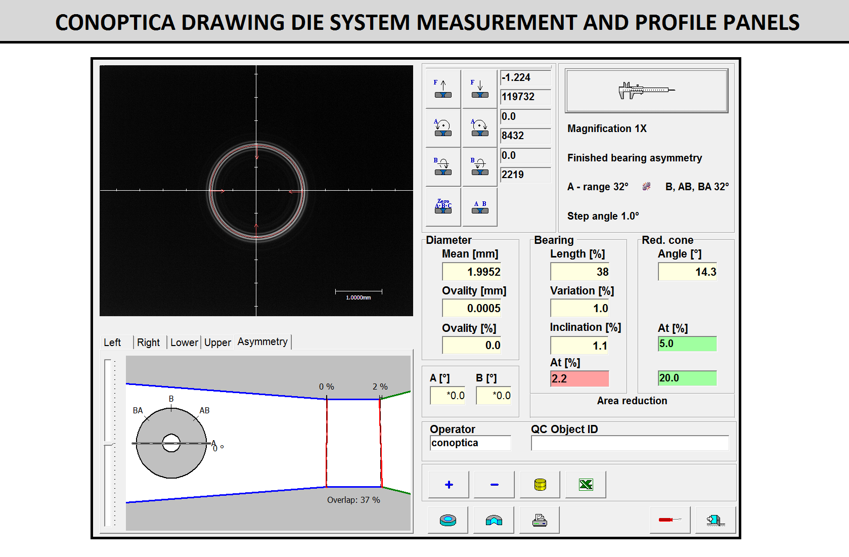
Conoptica systems measure both the die hole profile and diameter see (Figure Q12).
FIGP12&Q12
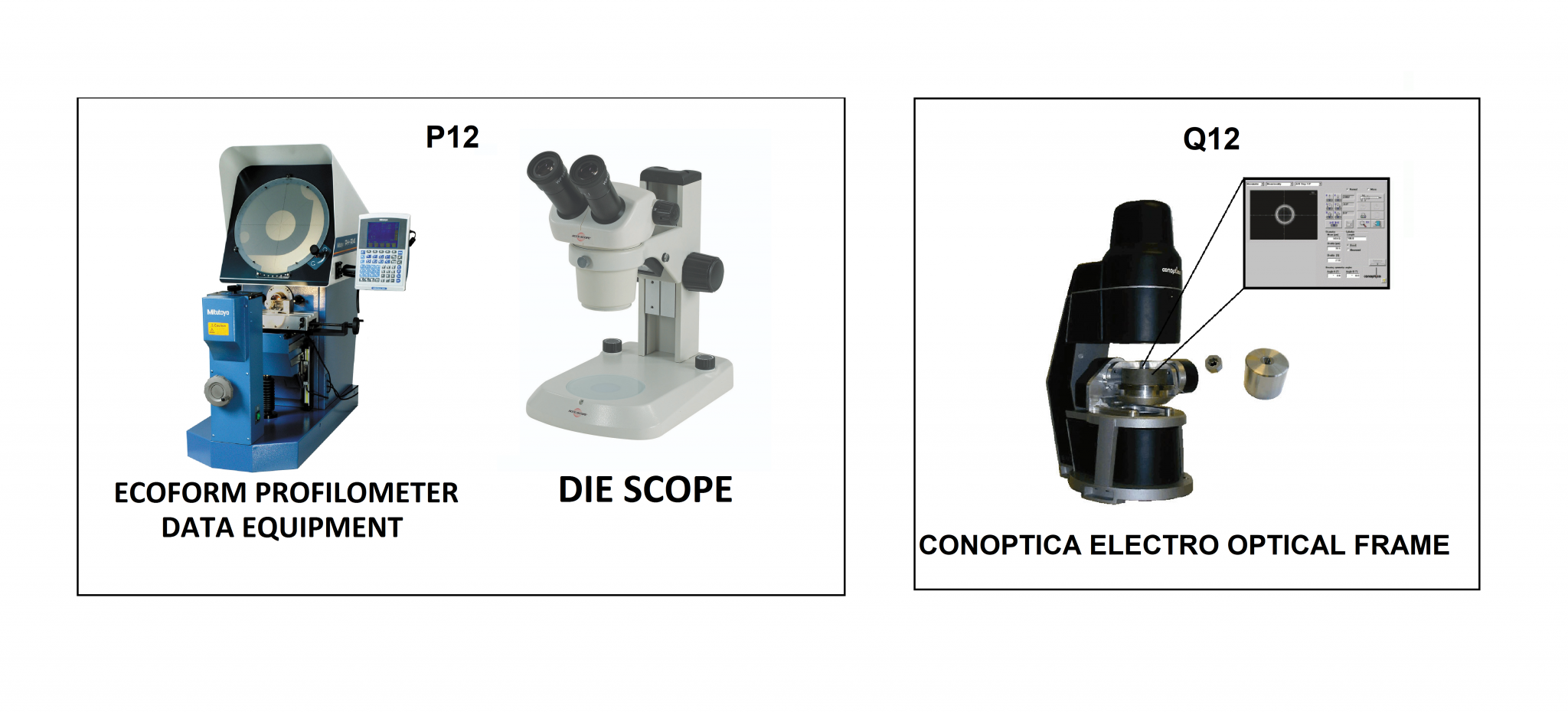
Conoptica system also directly measure the wire profile. These measurements are presented in the form of a profile graph and numerical values of the diameter, ovality, bearing length, and reduction angle see (Figure R12). The user decides where to measure the reduction angle and may select either the contact point of the incoming wire or another position along the reduction cone.
The system illuminates the die hole, or wire, from behind and observes from the front to collect measurement data. Three-dimensional data are obtained by tilting the die around two axes, thereby obtaining multiple stereoscopic views of the die hole. The system is fully automatic and is insensitive to die position and orientation. Die holes and wires from 0.0004 in. (0.01 mm) to 2.2 in. (56 mm) can be measured. All measurement parameters can be exported to databases and spreadsheets for further analysis, storage, and retrieval. A combination of precision opto-mechanics and knowledge of the light diffraction at convex surfaces produce accurate measurements.
Once successful die geometry is found, it must be produced accurately and consistently by quality die-making practices. Die making is not a difficult process if two conditions are met. First, the die manufacturer must have the correct machinery, and second, the proper manufacturing steps must be followed. Accurate measuring and thorough inspection in the die-finishing process produce high quality drawing dies.
The wiredrawing die is the only tool that forms wire rod into a drawn wire product to be shipped to a customer. When the die is consistently and accurately manufactured to a specified geometry, wiredrawing will meet production objectives. Dies will then perform better, give longer life, improve wire quality, shorten machine downtime, and lower labor costs. The investment in modern die finishing equipment is clearly an investment in higher wire productivity and product quality. The other option is to purchase quality finished die and return worn dies to a manufacturer with modern equipment and die manufacturing technology.
Note:
- RA is a measurement of surface roughness and the arithmetic average deviation from the centerline of the surface given in either micro-inches or micrometers (microns). RA x 1.11 = Root Mean Square (RMS) of the deviation from the centerline.
FIGR12