Wire Drawing Machine
Lift-Off Carriers (Strippers)
Spoolers (Horizontal and Vertical Axis)
Dead Block Coilers
Vertical Dead Block
Double Rim Capstans
Continuous Run
Introduction
The wire drawing process is a very important step in the production of welding consumables.This section introduces the types of wire drawing machines and methods for below products:
This chapter provides descriptions and general information on various types of wiredrawing machines –how they function and usual applications. The main focus will be on modern wiredrawing machinery, and the evolution of wiredrawing machinery to the current level of technology is discussed briefly along with comments on future technologies.
In the simplest terms, wiredrawing machines make wiredrawing dies effective. Actual wire cross-sectional area reduction occurs in the wiredrawing die.a wiredrawing die is remarkable for its simplicity and effectiveness. That the drawing die provides uniform elongation and reduction in diameter in a wire to a degree that cannot be obtained by any other method is integral to machine design features.
There have been consistent evolutionary advances in wiredrawing over the years, and some are more significant than others. Certainly, electrical power had an enormous impact on the advancement of wiredrawing. Improved equipment designs, such as internal water-cooled drawing capstans, and new engineering materials have improved machine drawing speeds and productivity. Other noteworthy technologies are direct cooling of wire as it exits the die, the Kobe Cooling System, and V-Trac machine, which uses the Kobe Cooling System and V-shaped capstans. These systems have shown potential, but significant problems have kept them from becoming practical manufacturing concepts. Basically, the major problem is removing residual water off the wire before entering the next die.
Another recent advancement has been the use of programmable logic control (PLC) and computers for machine control, fault diagnostics, and data acquisition. Sensor-arm or short stroke dancer-arm drawing machines are currently popular, having advanced from multi-sheave, dancer-arm machines. Significant changes in machine safety throughout the years have also been noteworthy.
Many experienced wiredrawing machinery suppliers today are European. Twenty years ago, Morgan, Vaughn, Marshall-Richards, Barcro, and OTT were common names throughout the industry. Today, none of these companies manufacture wiredrawing machinery, and common name are Koch, Frigerio, GCR Eurodraw, Hi-Draw, Engineered Machinery Company, and Lamnea among others. Capital equipment, such as wiredrawing machinery, is likely to last 20 or more years in continuous, hard operation. Therefore, replacement parts and after-sales services are major issues for end user consideration.
The clear motivation for improved wiredrawing technology is to attain higher productivity rates of quality wire. The continuous improvement of productivity rates of quality will result from a balanced effort between the raw material processing, wiredrawing die technology, lubrication, and machine capabilities.
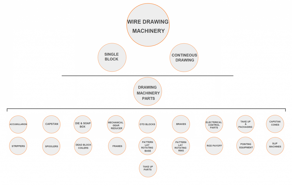
Types Of Wire Drawing Machines
Wiredrawing machinery may be classified as below :
A-single block machines
B-continuous drawing machines
Single Block Machines
The single block wiredrawing machine, generally use for sizing operations, is still the workhorse of many wire manufacturing companies.There are three basic types of single block machines:
1-vertical spindle push-up type
2-horizontal spindle
3-vertical spindle inverted capstan.
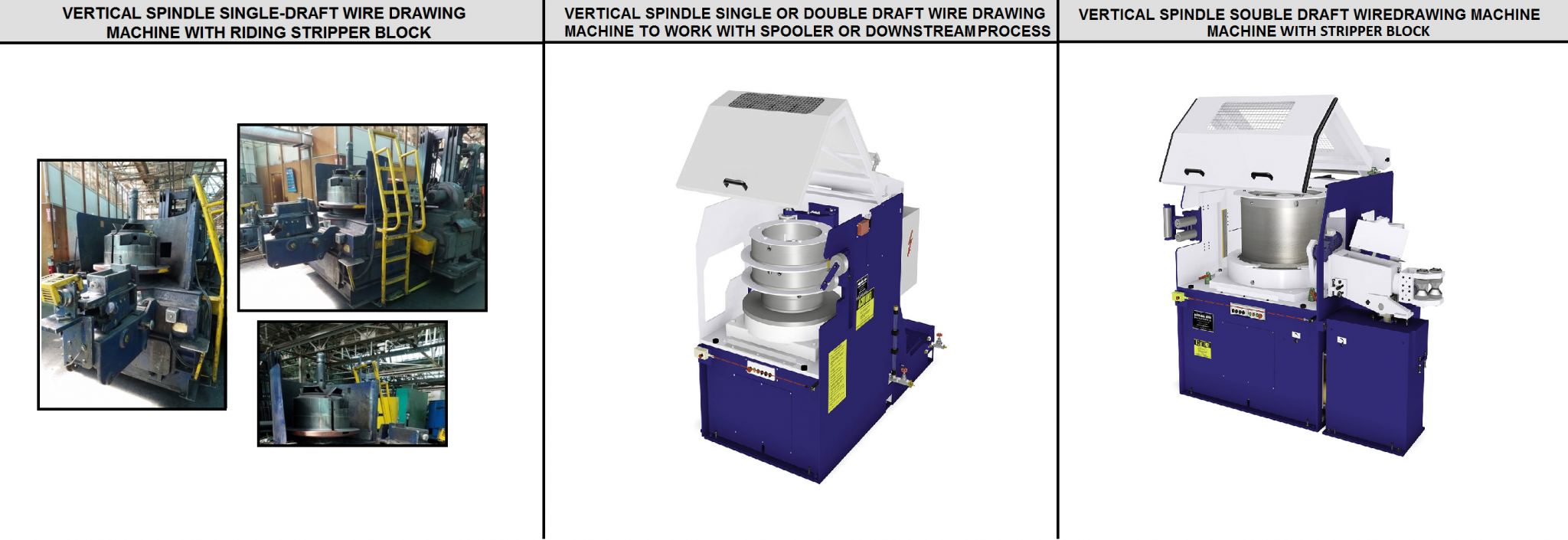
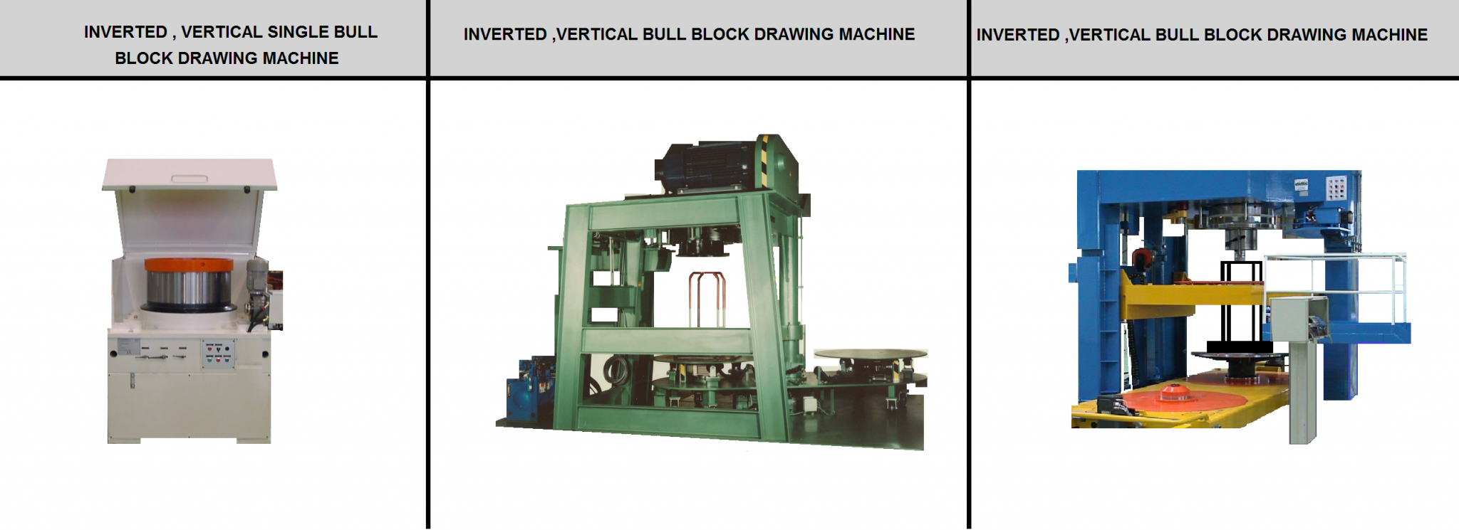
1-Vertical Spindle Single Block Machines
It designed with single- or double-draft capstan are widely used today; including many machines that are more than 50 years old. The machines are used for a wide range of rod sizes. In most cases the practical operating speed is limited by the payoff capability and/or the safe speed considering centrifugal forces working on the accumulated wire that is pushing up above the capstan onto the accumulation pins or riding stripper. The weight of wire accumulation is related to the push-up force, created at the draw line, by the area reduction at the die. The primary objections to the basic, vertical spindle bull block machine include damage to the wire surface and the inherent safety issues of the stripping operation. In some industries, such as concrete reinforcing steel, single vertical spindle block machines with one or two drafts are used to feed a large spooler instead of the more common stripped bundle. For large diameter or shaped wire, a push-up flange is incorporated to provide the push-up force. Examples of modern vertical spindle machines as well as the common, early vintage machine are shown in FigureA14.
FIG A14
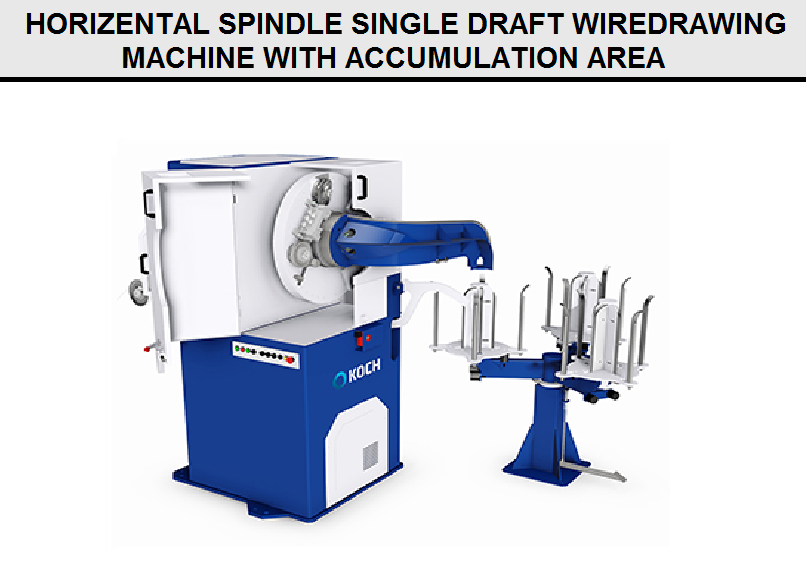
2-Horizontal Spindle Single Block Machines
It offer several advantages over the basic vertical machine. These machines are a good alternative to the vertical spindle machine for industries demanding superior surface quality. Early versions of the machine included a long, extended capstan section to hold accumulated wire for later extraction by a hairpin hook as shown in Figure B14. This system worked well, but the package size was limited to what could accumulate on the extended block. The next generation of this machine was to place a turntable or drum adjacent to, or in a pit below, the spinning capstan to collect coils of wire as they pushed off the end of the capstan. This design, coupled with a powered, automatic bending/feeding machine, provides a highly efficient and easy to operate system for large wires up to 2 in. (50.8 mm) in diameter. The wire bundle is removed from the collection drum after strapping with a stripper-like device that lifts only the weight of the bundle and does not have to force wire off of a tightly wound capstan. Manipulation of wire by hand is mostly eliminated. The pre-bending machine straightens the wire and pushes it into a power pointer or shaving pointer. Automatic grip jaws built into the capstan help start wire on the block, and a hydraulically adjustable die box automatically positions the die to maintain a nearly straight line pulling force through the drawing die as the coil starts. The box swings through an arc starting at the pulling grip and ending at the drawing line of the capstan. This feature helps prevent uneven die wear, which can lead to ovality of the finished wire.
FIG B14
3-Vertical Spindle Inverted Capstan Drawing Machine
It eliminates the need for a stripping operation as the wire is drawn onto an inverted capstan and allowed to fall onto a tunable fixed to a moveable wagon. The capstan can be supplied in a single- or double-draft arrangement as in a push-up style machine. Since an inverted block is a live block system, and accumulated wire bundle must turn at the full rotation speed of the capstan also, hence limiting the speed of this machine. Cascading coils and collected bundle of coils beneath the capstan are difficult to control at higher rotation speeds, as coils will attempt to fly out as they spin with the capstan. This problem has been addressed by automatically lowering the turntable to maintain a consistent falling distance for each wire loop. Using this system, machines operating at speeds up to 16 ft. per second (5 m/sec.) are able to achieve bundle weight of two tons (1,818 kg). Turntables can be driven separately by a synchronized variable speed drive or mechanically locked to the capstan. When separately driven, special winding practices can be employed by alternately increasing and decreasing the speed of the turntable driver to achieve a spiral lay pattern. Machines can be equipped with a double carriage, which allows starting an empty wire stem while the last filled stem is removed. Vertical inverted single capstan drawing machines are shown in Figure C14.
FIG C14
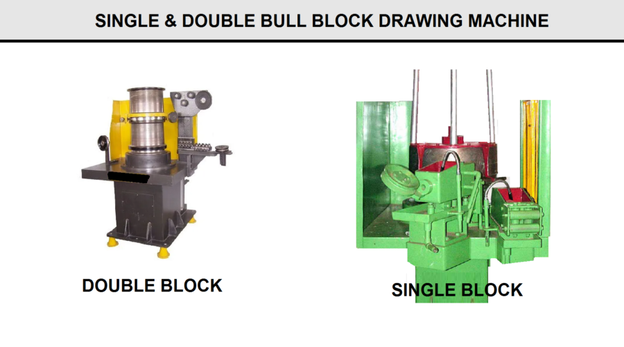
Single and double bull block drawing machines are shown in Figure D14. shows a single block machine having one die and the block set to have a riding stripper to remove wire and shows a double block machine having two dies and a collapsible riding stripper to remove wire. For the double bull block machine, drafting between the two dies must be accurate to control the bow going into the last die.
B-Continuous Drawing Machinery
When the desired wire physical properties require three or more consecutive reductions, successive operations on single block machines are not productive. Continuous or multi-hole drawing machines permit multiple reductions and improved productivity. A major hurdle in the development of continuous drawing machines was addressing the fact that wire speed exiting a drawing die decreased as die wear increased over time. Therefore, the subsequent capstan speed had to compensate for this change in wire speed. Early machine developers needed a system that precisely controlled the speed of each pulling capstan to match exactly the wire elongation caused by reduction in area. An alternative approach to this problem was to allow sliding or slipping on the pulling capstan when wire and capstan speeds differed. Continuous drawing machines, therefore, are classified as non-slip and slip machines. Non-slip drawing machines are usually for dry drawing and fall into four categories:
1-accumulation machines
2-full-stroke dancer
3-limited- or short-stroke dancer
4-back pull machines. Slip-type drawing machines are usually used for wet drawing
Most of the ferrous wire drawn today is done on non-slip, dry lubricant, multi-hole machines. The flexibility of today’s wiredrawing machines allows drawing a relatively wide range of wire sizes effectively as well as maximum productivity of a single- or limited-size range. Since, capstan cooling capability is critical, many equipment manufacturers recommend oversized capstans to allow longer contact wire and cooling time, which is very important for higher carbon steel wires.
Non-slip Machines– use capstans to pull wire through the dies, and there is no slip of the wire around the capstan during drawing. Capstan speed is matched to the speed of the wire exiting the die. However, as the die wears, drawn wire diameter increases and the exiting wire speed decreases. Therefore, the unavoidable difference between designed machine reduction and the actual die drafting must be compensated to prevent uncontrolled slack or tension of the wire between capstans. Accumulation machines are designed to allow wire to collect between die reductions. Hundreds of feet of wire may be accumulated on a block, thus allowing a number of loosely matched block speeds to operate continuously for significant time periods. Dancer machines are limited-accumulation machines since the accumulation is gathered over a series of fixed and moveable sheaves providing feedback to the electrical system to either slow down or speed up successive capstans and maintain constant mass flow. Back pull machines avoid any wire loops or accumulation through special torque control systems.
FIG D14
1-Accumulation Machines
It belong to a loose grouping of machine designs that generally are declining in use within the wire industry. However, these machines have been used so extensively over the years that significant numbers still operate today. Basically, this group includes all machines that compensate for capstan and wire speed error by controlling (or losing) additional loops of wire on the capstan.
Figure E14 illustrate schematically three methods of accumulation on the drawing block. Figure 5a shows an Overhead Take-Off (OTO) accumulator block. This system is commonly used as an accumulator block at the first position of a rod breakdown machine to provide extended running time in the event of an inlet snarl. The OTO configuration necessarily imparts one twist in the wire for every wrap of wire leaving the drawing capstan. If the succeeding blocks stop pulling, this will quickly build into a knot. This type of machine is quite flexible when using individual drive motors for each capstan. Accumulation of wire ensures a low wire temperature entering the succeeding dies accommodating a wire range of drafting practices. Required speed corrections for individual capstans are signaled by slow rotation of the flyer arm relative to the machine. For every rotation of the flyer arm relative to the machine body, one wrap is gained or lost on the capstan. Manual speed control requires the operator to monitor gains and losses on each capstan by viewing the rotation of the flyer pulley on top of the capstan. Automatic control methods continuously count the turns of the flyer in a PLC counter. The motor speed is adjusted to maintain the desired number of wraps. Line-shaft machines, where the same motor drives all capstans, must be drafted in such a way that each die is slightly smaller than what the machine gearing would demand. Therefore, the initial wire speed is slightly faster than the capstan linear speed. In this way, the preceding capstan will slowly gain wire on the capstan. When the block becomes too full, the inlet wire is cut and the machine is stripped. Machines equipped with declutching individual capstans can be helpful as long as the operator remembers to take wire off a stopped block. Stopping one block in the middle of a machine will quickly twist the wire into a knot. This OTO Block system is commonly used today on modern, non-accumulating machines as an accumulator block at the first position to provide some extended run time in the event of an inlet rod snarl.
FIG E14
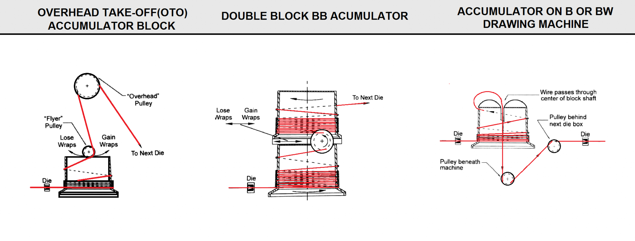
A double block accumulator, or BB block
These machines were important advancements for production of high carbon wire, such as the wire rope and pre-stressed concrete strand. Today, these blocks are employed as the final drawing block on some machines to provide accumulation time that allows spool changeover while the drawing machine continues to draw wire.
The Morgan B or BW machine uses a similar accumulation system as shown in Figure E14. The basic difference is that instead of wire going up over a stationary pulley, wire is turned back into the center, hollow shaft of the capstan, down to a stationary sheave beneath the capstan.
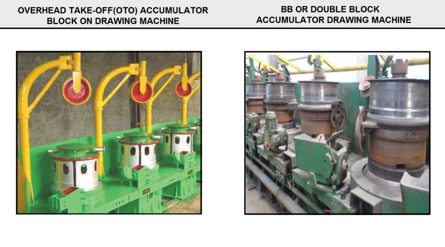
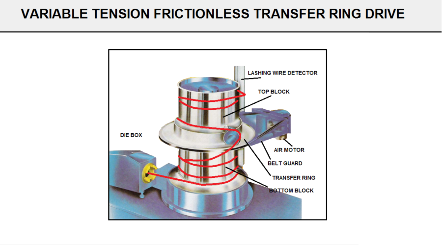
FigureF14 shows a drawing machine with an overhead take-off (OTO) accumulator block. Also figure shows a BB or double block accumulator drawing machine. BB accumulator with a motorized variable-tension, frictionless transfer ring drive has many benefits.
FIG F14
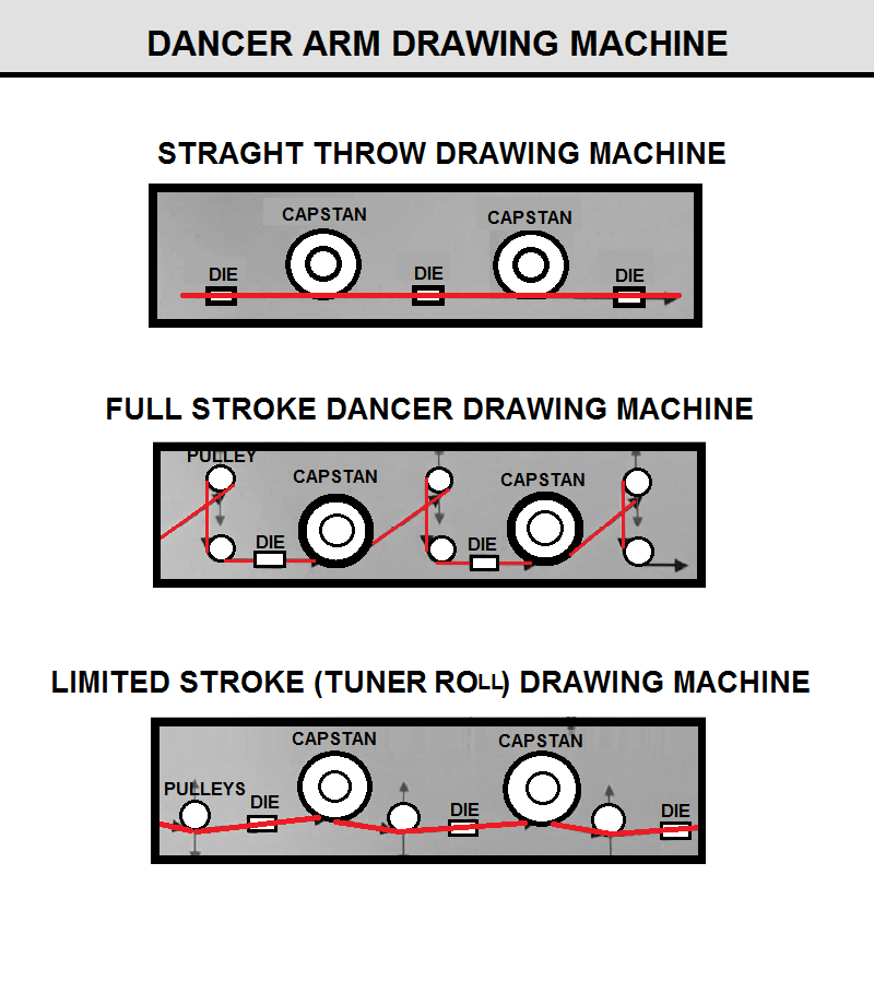
2-Dancer Machines
It can be classified as full-stroke dancer machines and limited-stroke (tuner roll) machines. Figure G14 schematically illustrates a straight through drawing machine, a full-stroke dancer machine, and a limited-stroke, or tuner roll, machine. In a straight through drawing machine, wire travels through the drawing machine in a straight line without twist, and there is very little bending of wire during operation. In a full-stroke dancer drawing machines, wire travels in a loop around a movable dancer arm pulley and a fixed guide pulley between each drawing block. When the block runs too fast or too slow, the loop decreases or increases and displacement of the dancer arm activates an electrical control system, which adjusts the block speed immediately. Dancer arm machines draw wire without twisting and are simple to control and to operate. The limited- stroke, or tuner roll, drawing machine is a combination of the straight through and full-stroke dancer drawing machines. The wire path is almost straight through but, like the full-stroke dancer machine, a guide roller monitors wire speed and sends signals to an electronic control system based on displacement of the guide roller.
FIG G14
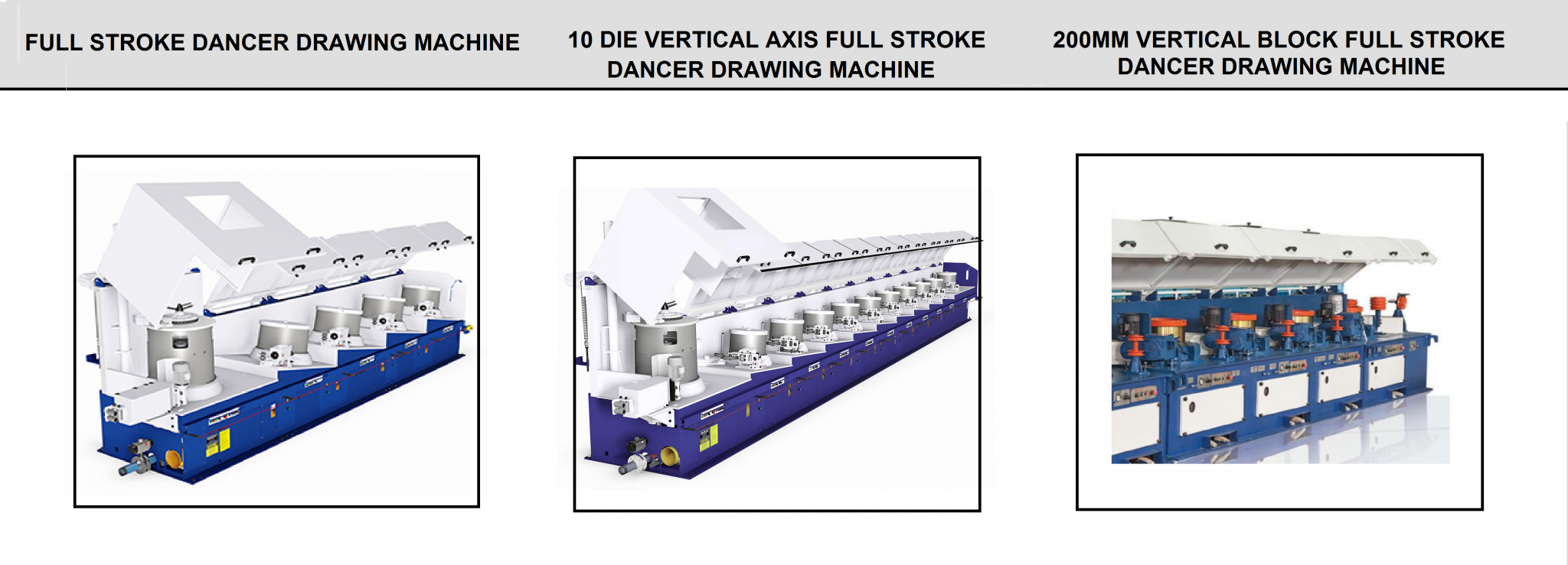
3-Full-Stroke Dancer Machines
It uses a series of fixed sheaves and pivoting or sliding sheaves to create the accumulator that is used to control capstan speed, maintain constant mass flow, and direct wire from one capstan to the next. Sheaves are designed for the largest wire size to be drawn through any given machine, and, clearly, the larger the wire the larger the sheaves. Sheaves are sized so that wire is not subjected to bending stresses.
Early dancer machines used large, power rheostats to control motor speed through direct control of the DC motor field current. Also, the early machines used spray ring cooling inside thick cast iron capstans, which wasn’t any better than the cooling offered by accumulator designs. An example of full-stroke dancer drawing machines are shown in Figures G14&H14.
Progressive improvements in electrical controls and block cooling gave dancer machines a clear advantage over accumulator machines. Although limited- or short-stroke dancer drawing machines are the overwhelming choice of current producers, full-stroke dancer drawing machines are often preferred for fine wire and/or in combination on a short-stroke dancer drawing machine at the finishing capstan(s).
FIG H14
Limited- or Short Stroke Dancer (Tuner Roll) Machines
It incorporates tilted-axis capstans that allow a direct wire path from the top of one capstan to the entry of the subsequent die box. One pivoting dancer roll generates a small deflection of the wire path creating the accumulation used for speed control. This arrangement eliminates the many sheaves that were required to redirect wire from one capstan to the next die box and thereby reduces the possibility for scratches or other wire damage. The small wire deflection (accumulation) of the short-stroke machine requires a responsive and accurate speed control system, which is enhanced by presetting the drafting schedule and individual capstan speeds in relation to each other. Advanced cooling methods, such as narrow-gap and other chamber cooling techniques, allow relatively small amount of wire to remain on the capstans. FIG R14 shows a BB accumulator with a motorized variable tension frictionless transfer ring drive.
FIG R14
Typically, limited-stroke dancer drawing machines have capstans mounted on vertical shafts, and the operator must lean over the machine and reach around the capstan to string-up. A limited number of companies manufacture machines with capstans mounted on horizontal shafts, which facilitates operator string-up, a distinct advantage for larger wire diameters and higher carbon steel. In addition most maintenance can be handled easily from the back side of the machine without having to crawl under the machine as may be required for some maintenance on vertical machines. Limited-stroke or tuner roll drawing machines are shown in Figure I14.
Modern drawing machines incorporate modular design, which permits customizing wiredrawing equipment for specific products and wire sizes. Figure J14 shows a modular four vertical block drawing machine. A horizontal machine with large diameter blocks (1270 mm) ideal for drawing larger diameter, high carbon steel wire, such as pre-stressed concrete stand, rope wire, etc., is shown in Figure J14. This machine design is easy to string up and maintain.
FIG I14
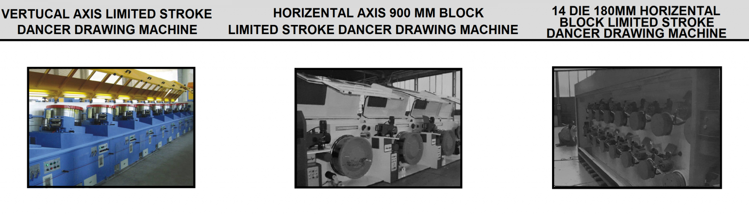
FIG J14
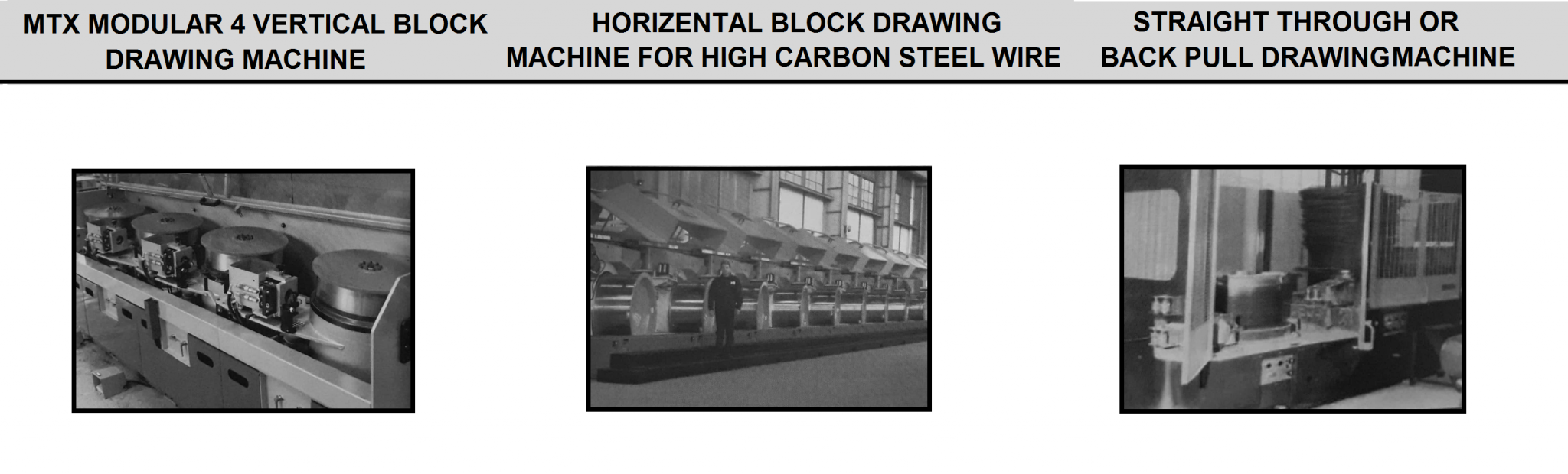
4-Back-Pull or Straight–Through Drawing Machines
It have been reintroduced to the market several times with limited success. The basic idea of these machines is that the wire path leaves one tilted capstan and makes a perfectly straight path through the next die to the drawing line of the next tilted capstan (see Fig J14). Comparing wire tension between the back of a die and the preceding capstan with current drawn by the motor driving the drawing block permits control of wire speed. Effective operation of the drawing machine results when each motor pulls its own weight. Sophisticated control systems today make the machine setup much easier for an operator. To date applications have had limited success to heavy machines for pre-stressed concrete wire and other high carbon products. However, this technology is receiving a lot of attention and may well be the design standard of future machinery.
The Modem Continuous Drawing Machine
Basic Drawing Machine Configuration
Basic drawing machine configurations and controls that distinguish modern continuous machine design are discussed below. When designing a machine to meet particular specifications, the first consideration is the product (wire) to be produced. If the particular product is within a narrow wire size range, the machine can be narrowly specified to maximize machine productivity while minimizing up-front cost. Conversely, if several different wire products will be produced, machine configuration must be compromised in each specification area. Other information used for design of a modem continuous drawing machine include the following:
- Material (wire)- Initial tensile strength, rate of work hardening.
- Machine speed- Determines maximum wire speed.
- Die pull- Maximum die pull dictates mechanical gear set size. Must allow for extra pull required for mechanical descaling and the pull from overhead pay-off towers and accumulators.
- Block diameter- Based on wire size at each pass, material, and cooling required.
- Machine reduction- Should be numerically lower than the minimum reductions planned. Setting machine reduction to match expected reduction per pass will maximize efficiency of each electric motor because all motors will turn at the same speed. However, machine speed will be limited when capstans are skipped or lower die reductions are used. Motors on early blocks will reach their maximum speed before the maximum machine speed is reached. Using a lower and tapered reduction for the machine will allow some block skipping while still allowing maximum machine speed.
- Motor power and speed- Die pull and wire speed determine the power required to draw wire at each capstan. Motor speed indicates motor .
- synchronous speed and maximum speed at which the motor can deliver rated horsepower
Machine frames are typically welded steel structures built to manufacturer’s standards and designed in three or four block sections that can be easily handled, contained, and installed. Capstans are mounted on tapered shafts either vertically or horizontally, depending on the manufacturer and application. Each capstan is driven individually through gearboxes and/or belts from the motor. Die boxes are adjustable on two planes and can be water-cooled and/or rotating, depending on the machine manufacturer and product requirements. Safety guards are installed and, depending on manufacturer and operating requirements, may be a fully enclosed environmental type or reinforced mesh type. Portals for soap access and windows for viewing operation are integral to guard design. Specific machine features are described below.
Capstan Cooling
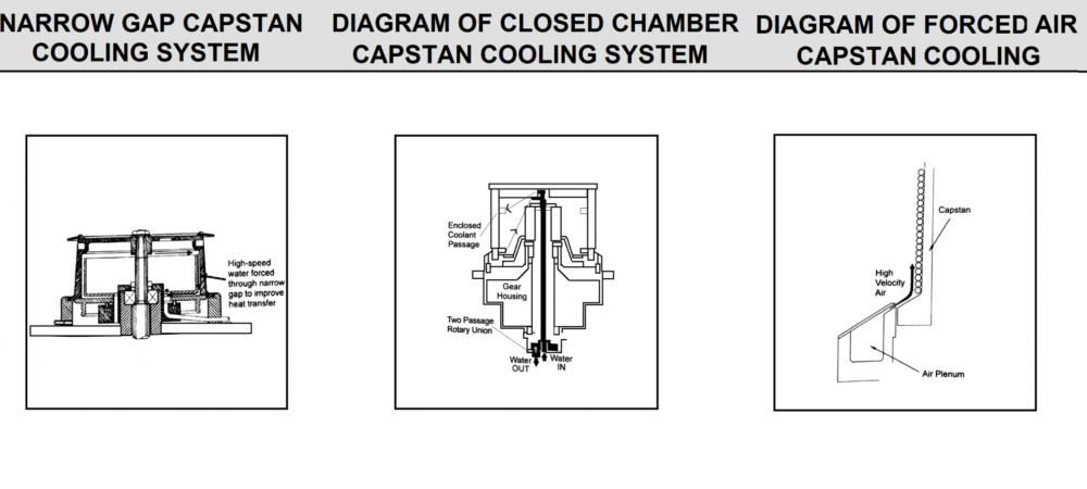
It is used for cooling drawn wire, and the most prevalent and trouble-free method is indirect cooling of the internal surface of the drawing capstan. Figure K14 is a schematic drawing of a basic narrow-gap capstan cooling system. For high-speed machines, narrow-gap capstan cooling is state-of-the-art, and it is offered in various forms by machine manufacturers. Systems are designed to induce high-turbulent water flow across the inner face of a capstan. High water turbulence maximizes heat transfer from the capstan (and hence the wire) into the cooling water. Typically, turbulence is sufficiently strong to limit buildup of deposits on the inner block surface, which, when present, significantly decreases heat transfer from the wire, through the block, and into the water.
For slower machines using capstan diameters greater than 29.5 in. (750 mm) narrow-gap capstan cooling is less desirable due to slow block rotation speeds. Slower block speed fails to achieve the high-cooling water turbulence necessary for the extra cooling. Current practice is to build a closed chamber capstan fed through a hollow block shaft through a two-way rotating union for these machines. This system is diagrammed in Figure K14.
When extra cooling is required, such as drawing very high tensile strength and/or large diameter wire, forced air-cooling may be added to the capstan(s) on the drawing machine. The most efficient method is diagrammed in Figure K14. This method forces high velocity air to travel up the surface of the accumulated wire, thus introducing air in the gaps between wire rings. Proper air-cooling is expensive to install and, ultimately, to operate due to the energy costs associated with operating the fans. Furthermore, extra air movement disperses airborne drawing soap around the machine that creates an environmental problem. Wire producers should critically examine the need for direct air-cooling before specifying this feature on a new machine. A water-cooled block with a 0.032 in. (0.8 mm) narrow-gap capstan could improve wiredrawing speed by 45% and, with an air blast, could provide 35% improvement in heat removal from drawn wire.
Other direct cooling methods have been tried over the years with varied success. Direct water-cooling must deal with lubricant that comes off the wire when splashed with water. Other methods use a light mist of water that removes heat through evaporation and leaves the wire surface dry by the time it arrives at the final package or the next die. However, both of these systems require high maintenance.
The basic idea when considering capstan cooling is to cool the wire as quickly as possible. Wire temperature at the top of the drawing capstan represents the starting temperature for the next reduction. Deformation in the next die adds heat to the wire, which is already at an elevated temperature. Critically important to capstan cooling is the amount of wire on the capstan, which translates to time for the cooling to occur. It’s also important that wire lay on the block surface without overlap. Larger capstan diameters provide longer residence time and greater cooling.
FIG K14
Accumulation Height
It is established by machine designers based on the additional cooling time needed for wire weighed against the ability to push wire up the capstan face in a neat and controlled manner. When a large amount of accumulation is desired, the capstan must have proper taper to allow the wire to advance without resistance. A loose and bushy wire bundle will payoff in an erratic manner on to the next capstan and cause the next dancer roll or sheave to oscillate. This phenomenon is not necessarily troublesome as long as the control system is properly tuned, but over time, it can cause machine instability and wire breaks. Accumulation height determines the amount of tilt at each capstan on straight line drawing machines.
Capstan Construction
This Type for the first continuous machines resulted in drawing blocks built to handle heavy drawing forces and years of service. Casting and construction methods tended to be unpredictable; therefore, the best chance of success was to make heavy and thick capstans. When water-cooling was first considered, it was a simple spray on the interior face of the capstan. The block was machined from a casting, and for low-speed operation, balance and precision were unimportant. Today’s machine presents a new set of challenges for the machine builder. The need for high cooling rates requires the capstan wall that separates wire from cooling water to be as thin as possible. Special materials for cast blocks or forged steel blocks are required that will not sacrifice strength. Heat-treating, or coating with wear resistant material, is used to harden the outer block surface. The machinery builder will select materials, hardening methods, and capstan designs, based on the wire products to be drawn.
Die Boxes or Soap Boxes
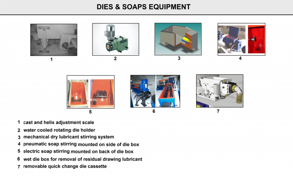
It provide a secure method of holding and adjusting a drawing die that allows wire to pass through a powdered (sometimes liquid or grease) drawing lubricant. Today, the basic function of a die box or soapbox is the same, but several additional features can be added (see Fig L14). Figure 1 demonstrates position indictors to provide basic reference for rough positioning of cast and helix adjustments. Figure 2 shows rotating die holders with direct or indirect water-cooling to provide consistent die wear, thereby improving die life. Figure 3 presents a mechanical soap stirring system providing adjustable agitation of drawing lubricant to prevent tunneling in the powdered soap. Pneumatic soap stirring mounted on side of die box is shown in Figure 4, while Figure 5 exhibits electric soap stirring mounted on the back of die box. Figure 6 shows a wet die box for removal of residual drawing lubricant, and Figure 7 demonstrates a quick-change cassette that allows positioning dies accurately in the cooling housing outside of the drawing machine. The cooling water circuit is made through quick couplings, thus allowing last die changes by using multiple cassettes.
Much has been said about the best method of die cooling, e.g., direct or indirect. Direct cooling refers to having the cooling water in direct contact with the outer case of the drawing die. Alternatively, indirect cooling refers to having the die sitting inside an additional metal sleeve, which in turn is cooled by the cooling water, thus eliminating any chance that water will come in direct contact with the wire or drawing lubricant. There is little doubt the direct cooling method results in cooler drawing die.
Some high carbon steel products, such as pre-stressed concrete stands, definitely require direct die cooling. If direct cooling is selected, using a quick-change cassette system will help to eliminate some water sealing issues. An operator can install new water gaskets in the die cartridge and test the assembly for a watertight seal before the cassette goes to the drawing machine. As a result, the actual time required to change dies is comparable to the quick-change possible with an indirectly cooled system.
The indirect cooling method eliminates operational issues resulting from water leaks around the die housing. Another operational benefit of indirect cooling is the quick die changes possible when using tapered pressure dies or die holders. The tapered die assembly is simply driven back into the soapbox and a new die goes back in the opposite way.
FIG L14
Mechanical Gear Reducers
It combined with belt and pulley reductions, regulates overall speed between the motor shaft and the block. The popularity of parallel shaft gear reducers, and their possible high ratios, have practically eliminated the need for primary reducers in front of worm gears when high reductions are required. The design engineer must select the gear reducer and belt drive that will handle the full power and torque presented by the die pull requirement. Furthermore, if the design relies on the gear unit to support the block shaft, extra support is required in the gearbox design.
Overhead Take-Off (OTO) Blocks
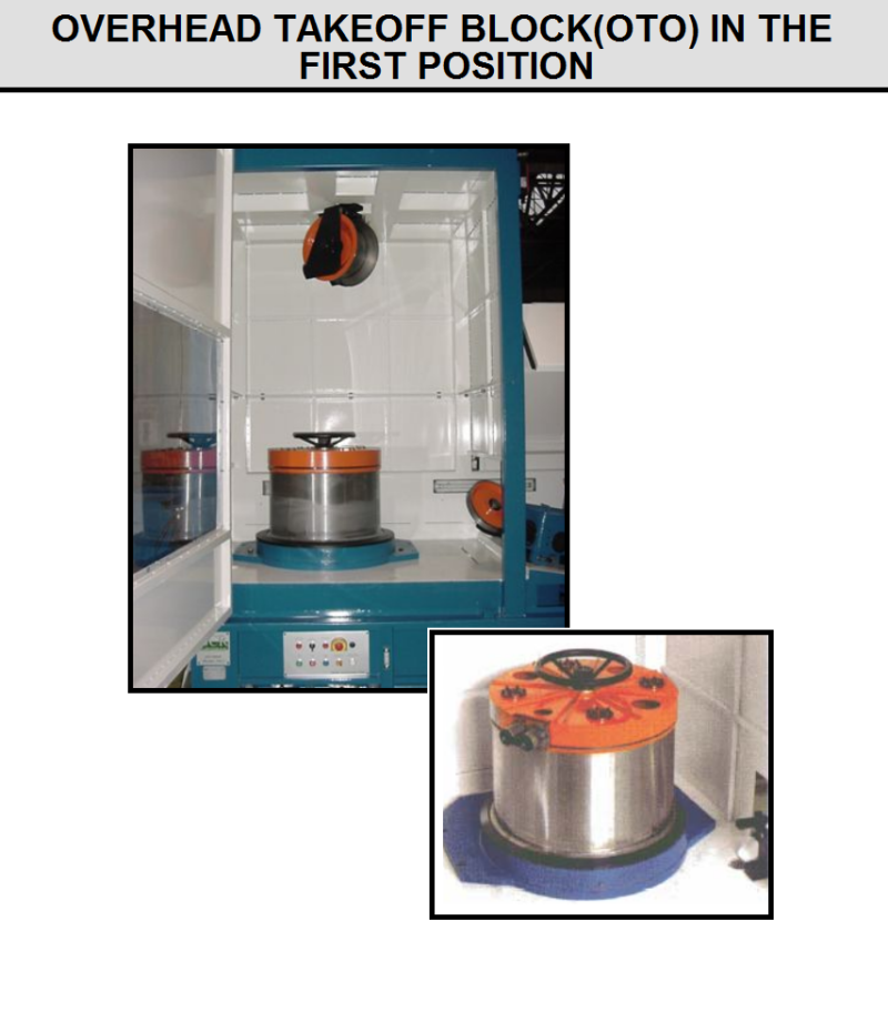
This model in the first two positions give the opportunity to work through an inlet wire snarl while allowing the finishing end of the machine to continue running (see Fig M14). Additionally, when there is a snarl, the electrical program can be set to stop the #1 block as quickly as possible without concern for wire breaks. This can mean the difference between an easy to resolve loop or a tightly kinked knot in the rod. Wire twist imparted by the OTO block does not present a problem in most cases. The first capstan can be tilted and a limited-stroke dancer provided to allow the option of stringing-up as a straight-line capstan or OTO as desired.
FIG M14
Brakes
They are very important in high-speed drawing machines that require advanced controls to operate at high speed, as well as advanced methods of stopping the machine under control. Typically, drawing machines have three modes of stopping:
- Norma stop provides maximum control with no stress on the wire. It is used when the package of drawn wire is full or the operator simply wishes to make a routine stop. The drawing machine simply slows down at a moderate rate until it stops.
- Fast stop is used when there is some urgent need to stop the drawing machine, such as a wire break detected on the machine or an inlet snarl when there is no OTO block. Mechanical brakes are applied in sequence to stop the drawing machine quickly without causing additional wire breaks. Regenerative motor braking generates massive amounts of electrical energy, which must be dissipated through large resistor grids in the form of heat energy. Older DC machines and advanced AC/AC machines can drive the energy back into the AC line. Since the motor drive is in control, the dancer/tuner stays active to the end of the stop sequence.
- Emergency stop is exercised when there is a dire emergency involving life or limb, and it is imperative to stop the drawing machine as quickly as possible. Machines with mechanical brakes simply remove motor power and immediately engage all brakes. Machines without brakes use the same technique as with Fast Stop, but with less dancer control. Wire breaks are likely in this stop mode.
Mechanical brakes can minimize the effects of wire ringing when the stationary wire actually backs up in the die due to dancer pressure from the preceding block.
Environmental Guards– minimize the escape of dust into the plant environment. A drawing machine can be built with factory installed air ducts to allow evacuation of burned soap and flying dust to a central suction/filtration plant. Machine guards can be fabricated from solid panels and fitted with sealing gaskets between guards.
Electrical Controls
The cost of electric motors and controls represents nearly one-half the value of a complete drawing machine. Therefore, the investment in electrical components must be thoroughly evaluated to maximize the value of the drawing machine. The features of the electrical components are covered below.
Variable Speed Drives
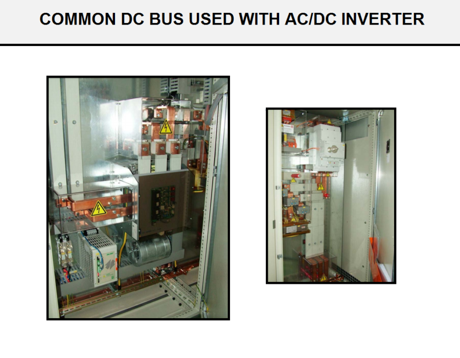
It accepts control signals in the form of run/stop and speed requests and converts electrical energy from the plant power system into the required electrical outputs to execute the control commands. The standard variable speed drive system today is an AC/AC frequency converter. One basic system uses a single AC/AC converter for each drive motor or a common bus system employing a large AC/DC rectifier unit to generate a DC voltage for all machine drives (see FigN14). From the common bus, DC/AC inverters generate the required power to each machine drive motor. The difference in these two configurations is not so important for a machine operator, as either system gets the job done.
FIG N14
AC Motors
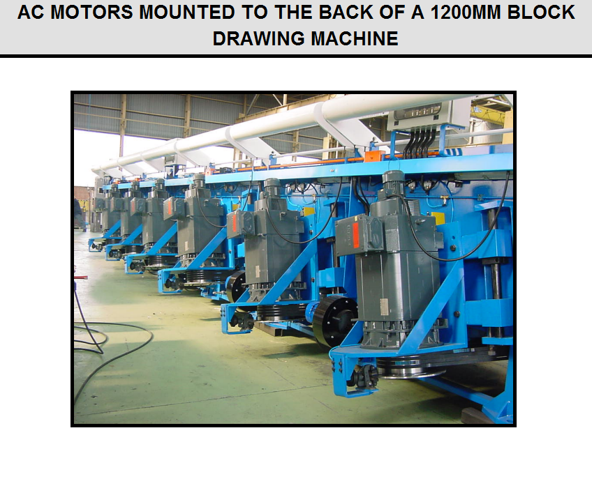
It used on drawing machines require special construction to endure the harsh duty and physical environment. Motors should be designed specifically for operation with the type of AC drive used. Internal windings in the motor must be designed to handle high voltage spikes generated in the drive, and separately powered cooling fan is needed to provide adequate cooling through the entire speed range of the motor. For smaller power systems (<7.5 kW per capstan), some manufacturers will choose nonventilated (TENV) motors that rely on massive amounts of iron in the motor structure to carry away the heat. Motors of this design are simpler for low power applications, but prohibitively expensive for large systems. Figure O14 shows AC motors mounted to the back of a 1200 mm block drawing machine.
FIG O14
Programmable Logic Control (PLC)
These systems of some type are used even in the simplest wiredrawing machinery today. Machines that have been designed with a few relay-logic control functions will use a PLC of the low cost and future flexibility it provides. The one major difference between manufacturer solutions today is the extent of machine control employed within the PLC logic. Some systems use PLC for all logical sequencing and timing of digital (on/off) signals, but leave actual speed control of each motor drive to separate control hardware or special speed control software loaded into an advanced variable speed drive internal processors. Other systems will use the power of an advanced PLC system to control nearly every machine control function, including speed and logic sequences.
Operator Interface and Controls
It used by machine operators to initiate machine commands must be well designed. A machine operator who finds machine controls to be logically positioned and functionally intuitive will be more likely to accept the new machine and to perform at maximum potential efficiency. No longer does a set of push buttons control each main drive motor with the only choice being either on or off. Now, an operator can select which drive motors will be left off and which will run. For example, to simply jog a drawing machine, an operator can choose between different types of jogging sequences as shown below:
- Fast Jog (entire machine)
- Slow Jog (entire machine)
- Jog single block
- Jog a block plus all blocks to the left
- Jog a block plus all blocks to the right
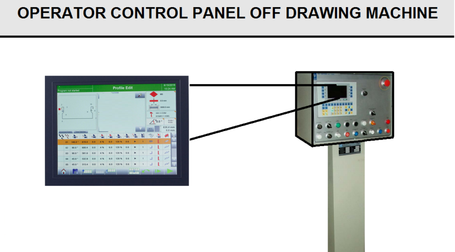
Operator controls should be arranged to facilitate selection of the proper switch each time, and furthermore, controls should be conveniently positioned as shown in Figure P14.
FIG P14
A Computer Supervisor- system
It should be supplied with each continuous drawing machine. The function of such a system varies for different manufacturers, but some basic features that are standard are:
- Plain-text messages regarding errors and causes of machine stoppages.
- Production data (inlet/outlet diameter, customer data, other specifications).
- Machine indicators (motor current and motor speed).
- Wire data (calculated wire diameter and die-to-die area reduction).
The main components of these systems are a basic operator interface and a full-screen personal computer based color display. A full-sized color screen offers many choices of data presentation. For example, die-to-die area reductions can be displayed in color bar graph format with different colors indicating deviations from acceptable criteria. On a basic drawing machine, these same data would be displayed as columns of black and white numbers. A PC-controlled drawing machine can be connected to a dial-up modem or even directly to a local plant-wide data network (such as Ethernet) so that production reports or trouble alarms can be e-mailed as required. There are innumerable possibilities for computer control and monitoring due to Input/Output (I/O) systems working with modern PLCs that can act like desktop computers and desktop computers that can act like PLCs.
Electrical Wiring- of a modern drawing machine is different than electrical wiring on a drawing machine manufactured in the past. Instead of hard wiring between motor drives and the PLC, high-speed data buses are used today. A single pair of data wires can carry hundreds of signals, thus saving valuable time and wire expense. In addition, many control signals from the drawing machine can be digitized at the draw machine and carried to the switch cabinet over the single pair of wires instead of a large bundle of control wires.
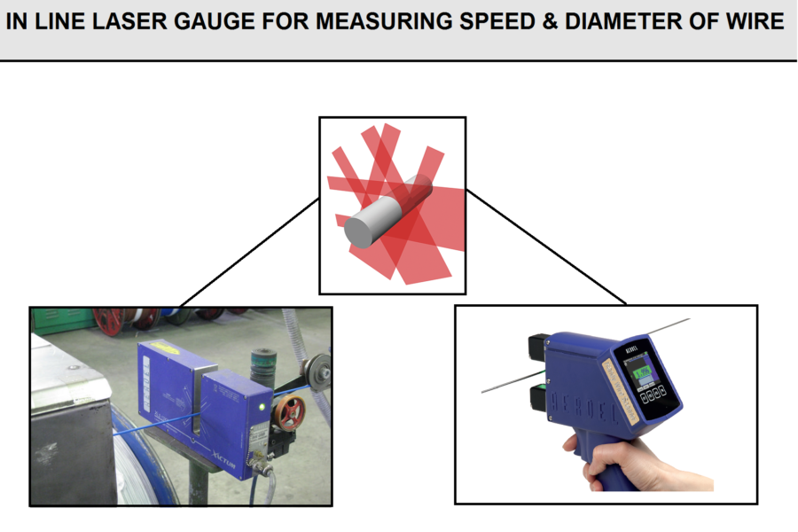
Advanced features include any continuous monitoring having an electrical signal output that can be incorporated into the control system. Common examples are monitoring wire diameter with laser micrometer, wire temperature with infrared sensors, water temperature with resistance temperature detectors (RTD) or thermocouples, rod defects with eddy current testing, etc. A self-cleaning laser measuring gauge is shown in Figure Q14.
FIG Q14
Take-up and Packaging Equipment
Wire must be properly packaged after drawing to satisfy the demands of the next process or customer. The final packaging equipment should enhance the efficiency of the overall production process. For maximum machine running time, heavy package weights are employed where possible. When package size is limited by customer specification, packaging equipment is selected to provide continuous operation or fast package changing. The numerous packaging solutions offered today preclude an adequate description of all the variations. Therefore, this discussion will focus on the main systems commonly used.
Lift-Off Carriers (Strippers)
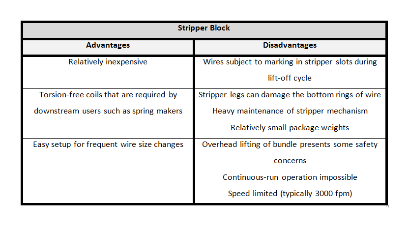
They are probably the least expensive and least efficient method of producing wire bundles to be delivered on tubular carriers. Riding strippers, where the lifting and releasing mechanisms stay on the drawing block while drawing the wire, have been replaced by the riding wire stripper design shown in Figure S14. Operation of the lift-off stripper is also illustrated in Figure S14. Vertical bars on the capstan support the wire bundle while running, and then the stripper is inserted to remove the wire bundle. The riding stripper presents safety issues as the heavy wire bundle is held in place by a simple latch mechanism. Package weights are generally limited by wire size because each new wrap of wire at the bottom must push the entire package above it up the block face. A general, albeit conservative, rule applied to stripper packages is that the wire bundle maximum weight is limited to 100 kg per millimeter (5.6 lbs. per 1X10⁻³ in.) of wire diameter. The advantages and disadvantages of a stripper block are summarized in Table 1.
FIG S14
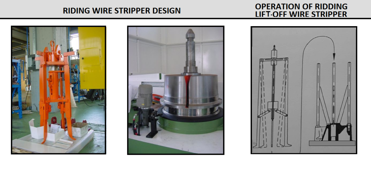
TABLE 1
Spoolers (Horizontal and Vertical Axis)
They are the only way to package wire today with modern high-speed drawing machinery reaching design speeds of 10,000 fpm (≈50 m/sec.). Other packaging methods simply do not allow speeds over 5,900 fpm (30 m/sec.). Spooler designs are classified by spool flange diameter and maximum package weight. Standard models typically range from 10 in. and 55 lbs., (254 mm and 25 kg) up to 55 in. and 11,000 lbs. (1,400 mm and 5000 kg) for single-spindle models.
Examples of vertical and horizontal spooling machines are shown in Figures T14. Figure 1 shows a two-ton, 1,000 mm vertical spindle spooling unit. A horizontal axis spooler is shown in figure 2. Figure 3 displays a dual-position, one-ton, 800 mm vertical spindle spooler with semi-automatic spool change allowing speedy replacement of a full spool. And Figure 4 shows an example of thread-lay precision spool winding.
There are several methods of traversing wire across a spool. Spoolers can be supplied with level-wind traversing systems having various levels of sophistication. Typically, traversing guides are powered separately by a variable speed motor drive, although the main spool motor powers many models through a gear change.
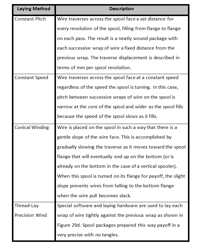
Wire may be laid on a spool with a constant pitch or constant speed level wind technique. Constant pitch is the only method available if the main spooler drive motor powers the traverse. Some methods of laying wire are summarized in Table 2.
Spooler motor power must be sufficient not only to drive the maximum weight spool at top speed while working against the winding tension, but also to accelerate that same spool to maximum speed from a stationary start. When adding a new spooler to an existing wiredrawing machine, extra care should be taken to ensure the acceleration time of the drawing machine is factored into the spooler horsepower calculation.
Spooler speed control is accomplished by using a festoon-type dancer. The amount of accumulation (stroke length of dancer sheave X number of wraps of wire X 2) required is inversely proportional to the acceleration time and installed horsepower. In the case of coarse wire, generally greater than 0.120 in. (3 mm), tension/torque control can be employed. Motor torque is regulated to provide constant pull on the wire. Special control boards or software programs are used to increase the motor torque control point as the spool diameter increases, thus keeping actual wire tension constant.
FIG T14
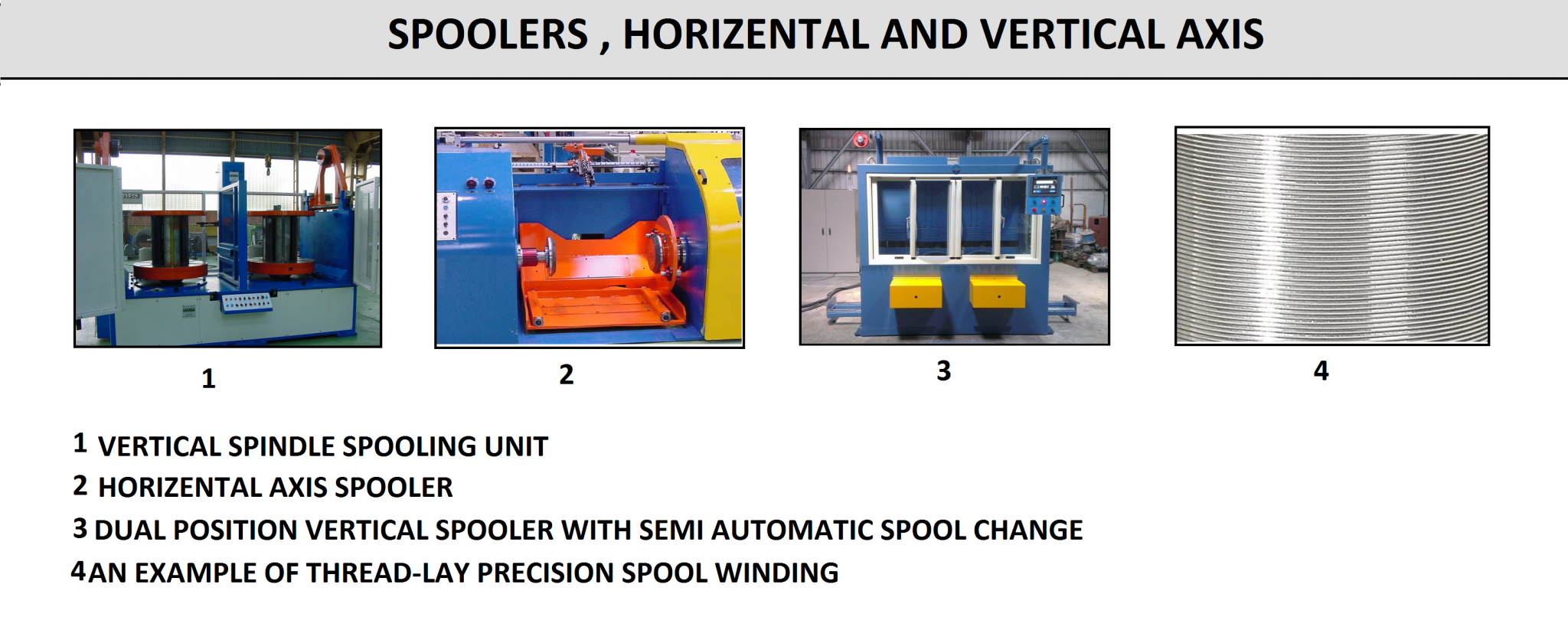
TABLE 2
Dead Block Coilers
They are the workhorses of the low carbon wire mill and the upholstery spring wire business, and to a lesser extent, the high carbon wire mill. Most machinery manufacturers offer some form of basic dead block coiler. Some even have different machine designs depending on whether the machine will be fitted with a drawing die or will simply coil wire. Dead block coilers are classified as either vertical or horizontal according to the orientation of the main shaft.
Horizontal Dead Block- machines have the drawing capstan affixed to the end of the main shaft supported on bearings, which allow the shaft to turn freely within the capstan. The purpose of the main shaft is to turn a flyer plate and support the capstan. The flyer plate supports the die box, sheaves, and straightening rolls. As the name “dead block” implies, the block or capstan does not rotate. Wire enters the back end of the main shaft, carries over a sheave in the center of the shaft and over one or two more sheaves to arrive at the periphery of the flyer plate. From here it is taken directly to the drawing capstan or through a drawing die. As the main shaft and flyer turn, drawn wire is looped in the vertical plane around the capstan. Drawing line radius and block taper push the wire away from the flyer plate. A gooseneck or laying arm carries wire away from the capstan to a point where it can flip 90 degrees onto a carrier bundle. Figure U14 shows a horizontal dead block machine with coil lowering and pattern laying. Figure V14 shows gear and belt-driven flyers on horizontal dead block machines.
As wire is wound onto the capstan, the inlet wire undergoes a single twist for each turn of the flyer. This twist builds up after a few wraps and pushes through the die and downstream to the final package. Management of this twist is one of the main challenges of dead block design.
What holds the block still? Most horizontal machines use a gooseneck arm to keep the capstan still. This is why the gooseneck turns clockwise (to the right as viewed from in front of the drawing machine) with its weight and pulling forces directed downward onto the wire carrier. For wire packages wrapped counter-clockwise, the gooseneck turns to the left.
Other drawing machines use back-turn gears to hold the block stationary. Back-turn gears, or sometimes toothed-belts, provide a planetary shaft or pinion running parallel to the main shaft and turning around the shaft at full rotation speed. The gear ratio between the block and the planetary shaft is duplicated in a gear set between the shaft and the machine frame. Thus, the capstan stands still. The cost to build this system exceeds the benefits for most horizontal dead blocks.
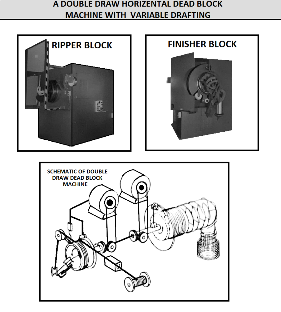
Figure W14 shows a double draw horizontal dead block machine with variable drafting between the ripper and finishing blocks. A self-centering dancer arm allows the ripper block to follow the finisher block whether coiling or drawing for reductions up to 30%. A schematic drawing of the double draw dead block arrangement is shown also in Figure W14.
FIG U14
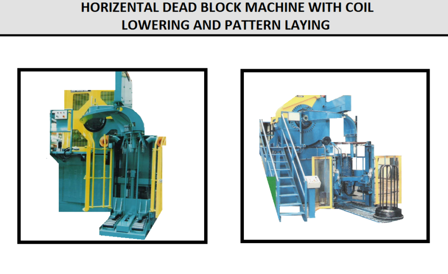
FIG V14
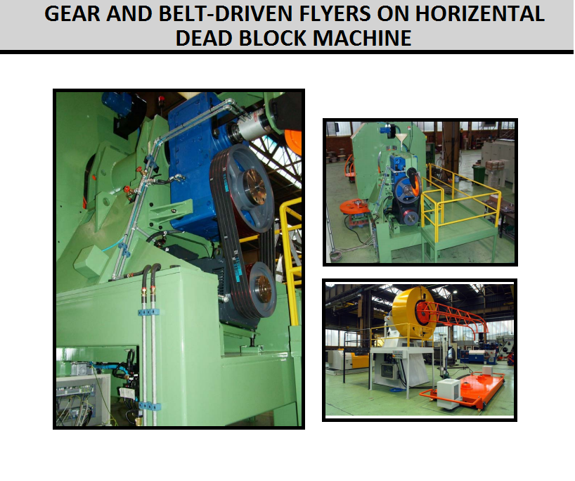
FIG W14
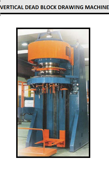
Vertical Dead Block
These machines operate in much the same way as horizontal dead block machines except that they use back-turn gears to hold the block stationary. The vertical machine arrangement provides an opportunity to place a wire carrier directly under the block. A special lowering system holds the wire bundle at a consistent dropping distance below the capstan for exceptional package quality for fine wires. Figure X14 shows a vertical dead block machine in which the drawing die and wire straightening rolls are mounted to the rotating plate. The device for lowering the wire bundle is located underneath the machine.
Modem horizontal and vertical dead block coilers have many features in common, several of which are covered below.
FIG X14
Frame
It is the basic structural component of a coiler.The frame must be strong to endure very large dynamic forces in machines designed for 5,900 fpm (30 m/sec.) operating speeds on 24 in. (600 mm) capstans.
Cooling- of dead blocks is difficult. Air-cooling along with capstan- and die-cooling is normally provided if the machine is to be used for drawing wire. Closed-loop cooling water systems are used to keep clean, treated water flowing through the rotating seals and the stationary block-cooling jacket.
Double Rim Capstans
They are used for fine wire coiling and drawing blocks. The first rim is used to draw wire onto the block through the die (if provided). Wire exits the first step after a few wraps and carries back out onto the flyer plate to be straightened or cast to the proper specifications. Wire then comes back onto the capstan to exit the machine. Wire cast and helix are set as much as possible by proper adjustment of the drawing die. Straightening is necessary to provide a dead flat wire package due to the natural wire twist in this machine.
Inlet rollers at the entrance to the main shaft help control twist. Sometimes a simple five-roll straightener is used to hold and to concentrate twist in a short length of wire within the main shaft. Twist is still there, of course, but this trick causes the twist to pass smoothly through the machine, rather than building up in a random pattern.
Continuous Run
during package change is a unique advantage of dead block coilers. Air cylinders and automatic controls lift the gooseneck and allow the carrier under the gooseneck to be replaced.
Pattern Lay-Rotating Base
It results in a high-density package that pays-off smoothly without tangles. By placing the wire carrier on a rotating base, the coil can be turned slowly, thus allowing each block-sized ring of wire to fall around the stem of the carrier in a rotating pattern. The carrier is tilted slightly or a special device is used to push each falling ring of wire against the carrier legs. Additionally, a pair of vertical rolls ride against the outside of the wire bundle to help shape a nice package.
Pattern Lay-Rotating Ring + Lowering Table
They can be employed in either vertical or horizontal machines. The ultimate package quality is obtained when each wire ring falls an equal height. A pair of arms is raised above the carrier at the start of the package and is lowered 2-3 in. (50-75 mm) each step as the wire bundle builds. The result is that the top of the package is maintained at the same height. Because the arms hold the package, the carrier must stand still. To achieve a pattern-lay, an eccentric chute is slowly turned above the top of the carrier to push each ring against the stem.
High-Speed Operation
High-speed operation at speeds greater than about 4,000 fpm (20 m/sec.) requires special design considerations. Motor power must be increased, and the basic machine frame must be strengthened to handle heavy loads rotating at high speeds. In some cases, special carbide slides are substituted for the rotating pulleys and straightening rolls. Because they do not rotate, slides improve the overall machine balance and avoid problems of short bearing life normally associated with rotating machines.
Other Wire Mill Equipment
The continuous drawing machine is a large investment. Therefore, it is important to use the most efficient and productive auxiliary equipment, such as payoffs, take-ups, and pointing machines, in order to achieve the maximum return on equipment investment.
Rod Payoff
Rod Payoff design has advanced to match the increased finishing speeds of modern wiredrawing machinery. Essentially two basic methods of rod payoff are used-flipping from stationary coils or unreeling from rotating coils as shown in Figure Y14.
FIG Y14
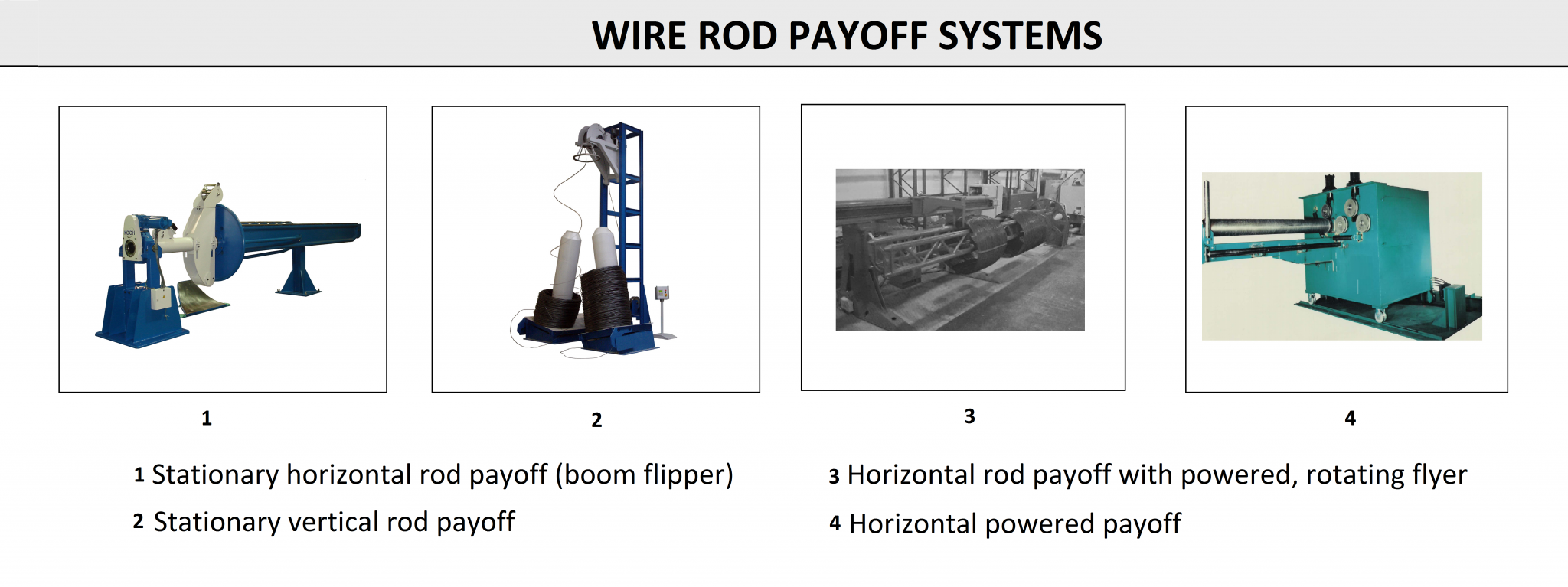
Stationary Horizontal Rod Payoff (Boom Flipper)- is the traditional method of rod payoff into a drawing machine (see Fig 1 in Fig Y14). The system works well up to 600 fpm (3 m/sec.) for reasonable quality rod coils and possibly faster for very good coils. Since the coil is stationary, it can be welded end-to-end continuously when two flippers are used. The stationary coil imparts one full twist in the rod for each wrap that flips off the payoff. This is not a problem for most multi-hole machine operations because stress from the twist is dispersed in the multiple drafts. Rod passes through a ring mounted to a heavy weight to detect snarls in the rod. An electric sensor picks up the ring movement when a knot tries to pass and stops the drawing machine.
Stationary Vertical Rod Payoff provides increased operating speed and valuable space savings (see Fig 2 in Fig Y14). Gravity helps stretch and straighten coils as they rise to the top pulley, and this helps rod make the turn and enter the machine without tangles. Snarls are detected by a paddle on the top pulley or by catching the snarl in a small guide ring. When the wire pulls tight, a moveable pulley shifts due to increased pull and detects the snarl. This system has been used for high carbon rods with some success, although the high carbon application is difficult. Special hold-back rings, straightener rolls, and clicker bars can be used to improve the operation by sorting the rings and straightening the rod.
Vertical Rotating Base Rod and Coarse Wire Payoff is a slight modification of the stationary vertical rod payoff method. In this case, the coil is rotated as the wire pays out, and it can be used for rod or heavy wires. Turning the coil unwinds the twist imparted by the overhead payoff. However, since coil bases are rotating, the operator must stop the bases in order to make a weld.
Horizontal Flyer-type Rod Payoff- is used in some high carbon applications when high speeds and continuous operation are required (see Fig3 in Fig Y14). The system tightly controls the rod at all times so snarls are minimized. Continuous operation is achieved by adding new rod coil to the back of a long boom. The boom pivots at the flyer-end and rod slides forward by lifting the boom or by using a coil-pusher. The flyer arm may be secured with a brake or driven by a variable speed motor.
Powered Feeding and Straightening Payoff is for heavy rod feeding single draft operations requiring very careful attention to the rod surface (see Fig4 in Fig Y14). This machine is used for drawing coil bar feedstock. A long extended boom rotates with the rod coil to help it payoff, and a series of rollers helps separate the end of the coil from the rod bundle. As the drawing machine pulls the rod, a dancer arm under the boom senses the last wrap as the feeding end of the coil grows smaller. An electrical signal from the dancer causes the boom drive to rotate faster to push more wire in the direction of the drawing machine, thus opening up the last wrap. A set of straightening rolls can be employed to provide straight wire to the drawing machine and pointing operation.
Pointing Equipment
It is required to make a sharp point on the leading end of a wire or rod so that it may be threaded into the drawing die.There are three common methods to make a point, rolling, shaving, and swaging (see Fig Z14).
FIG Z14
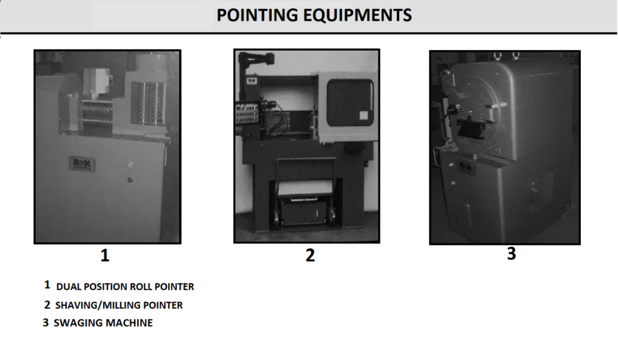
Multi-Groove Roll Pointers- are used to roll a wire end between two grooved rolls to cold/warm work wire to a smaller diameter (see Fig 1 in FigZ14). The wire must be turned 90 degrees between each pass to keep the resulting wire end relatively round. Succeeding passes use smaller and smaller grooves in the rolls. A hand-operated roll pointer is commonly used for wire sizes smaller than 0.22 in. (5.5 mm). Larger sizes require motorized rolls to point high carbon steel wire, but an operator still must turn the wire 90 degrees between passes. However, when pointing very large wire rods, vertical and horizontal pairs of rolls automatically turn the rod rather than manually manipulate the stiff material. Powered pointers frequently have a heavy shear to make a clean cut on the wires.
Shaving or Milling Pointers- are effective working with a powered payoff to point a large diameter rod in a single pass (see Fig2 in FigZ14). The milling cutters simply shave off the required amount of steel to allow the point to enter the drawing die. This machine can create points up to 6.5 ft. (2 m) long.
Swaging Machines- effectively reduce wire to a smaller diameter by using swaging dies with a circular profile determined by the wire/rod diameter (see Fig 3 In FigZ14). Unlike the shaving machine, wire is actually deformed to the smaller diameter; therefore, the operation does not generate waste material such as chips and shavings. A swaging machine can create point lengths of 6.5 ft. (2 m) or longer.
Process Line Take-up Equipment
It is not actually part of the wiredrawing process. Multi-wire process take-ups incorporating stationary capstan (dead block), rotating capstan (live block), and accumulation block spoolers are commonly used in galvanizing and heat-treating lines (see Figs A15-1).
Stationary Capstan Take-Ups (Dead Blocks)
They are typically used to take-up annealed and galvanized low carbon steel wire, patented and phosphated or galvanized high carbon steel wire,and annealed stainless steel wire (see Fig1 in FigA15-1). This equipment can also take up hard- drawn low and high carbon steel wire. The main advantage of these take-ups is the possibility of obtaining pattern-lay coils by rotating an inclined turntable holding the carrier at a very low speed. A pattern-lay package produces significantly increased coil weight and reduces snarls in subsequent payoff processes. Depending on the machine type, pattern-lay wire can be collected on carriers, in drums, or into catch-weight coil bundles.
The basic take-up machine is available with either a V-groove capstan or a flat capstan. While the V-groove capstan is used in most applications, the flat capstan is typically used for fine diameter wires. The following options are offered for stationary capstan take-up machines:
- Dual size (stepped) V-groove capstans, one mounted under the other, to improve application range.
- Pneumatically operated wire accumulators and wire length counter, to produce coils with constant weight and to facilitate carrier unloading/loading.
- Pattern lay turntable equipped with pneumatic unloading/loading.
Rotating Capstan Take-Ups (Live Blocks)
They are typically used to take up hard drawn and galvanized low or high carbon steel wire, large diameter annealed and galvanized low carbon or patented high carbon steel wire, annealed stainless steel wire, and oil-tempered wire (see Fig2 in Fig A15-1). The use of a rotating capstan take-up is essential under one or more of the following conditions:
- Large wire diameters up to 0.71 in. (18 mm).
- Tensile strength over 217,500 psi (1500 MPa).
- Twist is unacceptable in the finished product.
V-groove or flat block capstans are available in these take-up machines. A flat capstan is used when a drawing die is required. V-groove blocks use multiple wraps and come with a pressure roll. Choice between the two types of capstan is made according to wire surface quality requirements and type of wire coating used. Typical options include:
- Dual size (stepped) capstans, one mounted under the other, to improve application range.
- Drawing die with dry or liquid lubricants.
- Motorized turntable rotating the carrier slightly slower than the capstan increasing wire cast compared to capstan size, thus allowing heavier coils.
- Pneumatically operated wire collecting arms accumulate wire while an empty carrier is positioned.
- Turntable unloading/loading device.
- Special pattern lay for use with a rotating capstan take-up for low speed operations, e.g., stainless steel annealing. This enables significantly increased coil weights and facilitates subsequent payoff process. Pattern-lay is achieved by rotating the turntable on an orbital axis in conjunction with the capstan rotation.
- Spiral lay for large diameter wires by alternately increasing and decreasing turntable speed compared to the corresponding capstan speed.
Accumulation Capstan Spool Take-ups and Payoffs
They are typically used to payoff and take-up annealed and galvanized low carbon steel wire, patented and phosphated or galvanized high carbon steel wire, hard drawn and galvanized high carbon steel wire (ACSR), patented and brass-coated high carbon steel wire (tire cord), hard drawn and bronze-coated high carbon steel wire (bead wire),and aluminum-clad high carbon steel wire (see Fig3 in Fig A15-1). Accumulation capstan pay offs and take-ups are essential when changing spools without stopping the process. Accumulation capstan spool take-ups use the basic accumulation block concept employed in accumulation drawing machines. One big difference is that the accumulation arm is driven by an AC inverter drive to control wire tension precisely. Typical options include:
- Motorized traverse speed/pitch adjustment.
- Self-regulating traverse width control.
- Full or semi-automatic spool change.
- Spool lifters to handle multiple spool sizes and cylindrical bore spools.
Slip Machines
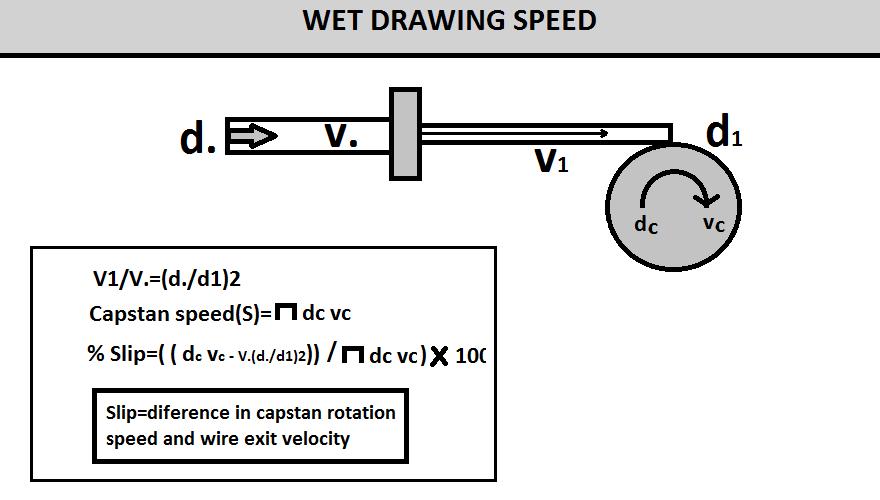
In production, the actual wire size will deviate from the original size of the drawing die through which it is pulled. Therefore, wire speed, which is proportional to the square of the diameter, will not match the angular velocity of the pulling block (see FigB15). The wire will slip when the linear speed of the pulling block is faster than the wire speed, which decreases as the wire diameter increases due to die wear. The term “slip” refers to the percent difference in capstan rotation speed and wire exit velocity.
Most of the early continuous drawing machines were slip machines. These drawing machines had a series of pulling capstans driven at fixed speeds with the speeds increasing towards the finishing end of the machine to compensate for wire elongation during drawing. Wire passed through a drawing die and wrapped around the pulling capstan a couple of times before entering the next die. This process was repeated until the finishing block was reached. No attempt was made to synchronize speeds of the wire and pulling capstan so that the wire slipped on the capstan. Due to heat generated by this slippage and the possibility of surface damage on the wire, the process today is limited to wet drawing machines. Slip between the capstan and the wire is facilitated by limiting the number of wraps around the pulling capstan and wetting wire and capstan surfaces with drawing lubricant.
FIG B15
Capstan diameters for wet slip drawing machines used today are commonly designed for a constant reduction per die. Reduction in each die (r) is related to the ratio of wire diameter before (d0) and after (df) the die according to Equation 1.
As shown in Figure , the ratio of wire speed before (V0) and after (Vf) each die is inversely related to the square of the ratio of the wire diameter before (d0) and after (df) the die according to Equation 2.
Since linear speed of a capstan is monotonically related to capstan diameter as shown in Figure, reduction in each die is related to the ratio of the capstan diameter before (D0) and after (Df) the die according to Equation 3.
Therefore, Equation 4 gives wire speed exiting a die as a function of wire speed entering the die and capstan diameter before and after the die.
EQUATIONS
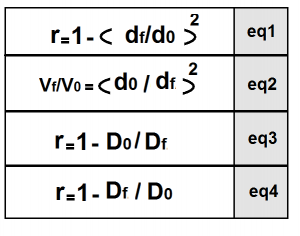
For example, if a machine is designed for 15% reduction in each die, the ratio of capstan diameter before and after each die will be 0.85 and the wire speed exiting the die will be 1.18 times the wire speed entering the die. Since reduction does not actually remain constant due to die wear, drafting is usually made with 1-2% higher reduction, which results in some slip between the capstan and wire. The die wear tolerated depends on the amount of slip possible. If the pulling capstan speed exceeds the wire speed more than can be compensated by slip, the wire will break.
There are two types of wet slip drawing machines: tandem machines and capstan cone machines. Capstan and dies are lubricated by tilting immersion, flooding immersion, or spraying.
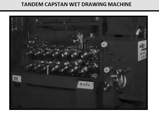
Tandem Capstan Wet Drawing Machines
They have pulling capstans with the same diameter so that each succeeding capstan rotates with a specified increase in speed to compensate for wire elongation. The required speed increase is built into the total gear reduction to each individual capstan. Figure C15 shows a tandem capstan wet drawing machine with tilting immersion lubrication and an integrated horizontal spooler.
FIG C15
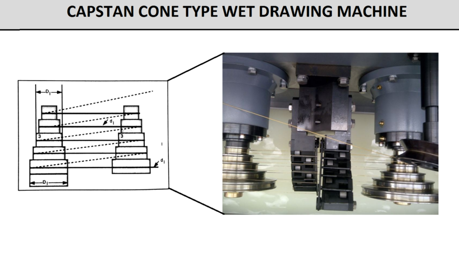
Capstan Cone Wet Drawing Machines
They have a series of drums or capstans mounted on the same shaft with each succeeding capstan larger than the preceding one to compensate for increased wire speed (see FigD15). Increased capstan linear speed results from increasing diameters of the capstans mounted on the common drive shaft. Cone-type drawing machines can have multiple pairs of cones providing 10 to 32 drafts in the machine (see FigD15). Each successive pair of capstan cones has the same dimensions, but each is driven at higher rotational speed. Manufacture of capstan cones requires expensive machining compared to tandem capstans, which are all the same size. However, mechanical drives for the capstan cones are simple compared to complicated gear or belt reduction systems required for tandem capstan machines. Most wet slip machines built today are the cone type.
The most demanding wet-drawn products (tire cord wire and spring wire) require excellent alignment between the wire path and the die centerline. Common capstan cone machines are arranged so that wire enters a die every time it passes from one cone to the other (both top and bottom). For the most demanding applications, machines are built with only a die on the top pass between cones. The wire pass line between capstans through the die is perpendicular to the cone axis, thus assuring a well-aligned inlet to the die. The bottom pass is used to make the horizontal offset between steps on the cones. This system has the advantage of more cooling time between die passes. In most slip drawing machines, the final capstan is a dry capstan using an adequate number of wire wraps to provide positive, non-slip pulling force. This final capstan can be water-cooled.
In wet slip drawing machines, the dies, wire, and slipping surfaces of the capstans must be continuously supplied with fresh drawing lubricant. The three basic methods of accomplishing this are tilting immersion, flooding immersion, and spraying. In the tilting immersion wet slip drawing machine, lubricant is held in a bathtub-like container and drawing cones are tilted or rotated into the lubricant during operation. During string-up, capstan axes are horizontal, while during wiredrawing, they are vertical (see FIGS D15). Flooding capstans with lubricant is used when the drawing machine complexity does not readily allow tipping or rotating capstans into a lubricant bath. Watertight doors are fixed to the front of the machine and lubricant is pumped to a level to cover the capstans. Alternatively, capstans are simply immersed in a tub filled with lubricant, which is drained to access the capstans for string up. The spray-type systems are commonly used only in ultra-fine wiredrawing applications. In this case a steady stream of lubricant is pumped to the back of the die and the capstans. Complete coverage of the capstans by tilting or flooding is the preferred method for most applications.
Lubricant for wet slip drawing machines can be supplied from a common, central lubricant management system, or the machine may obtain lubricant from a local reservoir. Cooling the lubricant, filtering to remove contaminants, and adding biocide to control bacteria growth are common lubricant maintenance practices. Actually, proper temperature management rather than cooling should be the goal. Some wire mills find that heaters installed in the lubricant improve productivity coming off of a mill shutdown because drawing can be started with the lubricant at the optimum temperature.
FIG D15