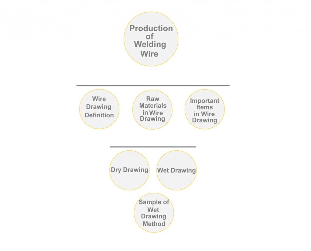
Welding Wire Manufacturing
1) Annealing
2) Pickling
3) Drawing Line
1) Annealing
2) Pickling
3) Drawing Line
Introduction
The use of welding wire process has grown rapidly and has always replaced the old methods in recent years. These methods have high efficiency and speed and will be capable of welding in robotic mode. This property is very important because many industries with high production circulation such as automobile manufacturing, construction of heavy structures, tanks, pipes and so on have turned to the use of robotic welding due to its many advantages.
It is also possible to use these method in welding all Ferro and non-Ferro alloys with the corresponding welding wire. In the following, we will introduce methods of producing different types of welding wires consist of:
-Gas Metal Arc Welding Wire (GMAW)
-Gas Tungsten Arc Welding Wire (GTAW)
-Submerged Arc Welding Wire (SAW)
It is recommended to read this after reading this article to learn more about different production methods. It is an example of a dry drawing method in 3 steps (Rough Drawing – Fine Drawing -Re Spooler) to produce 370 tons of welding wire (ER70S-6) per month. The linear dry drawing line for manufacturing this kind of product is also described .
Wire Drawing Definition
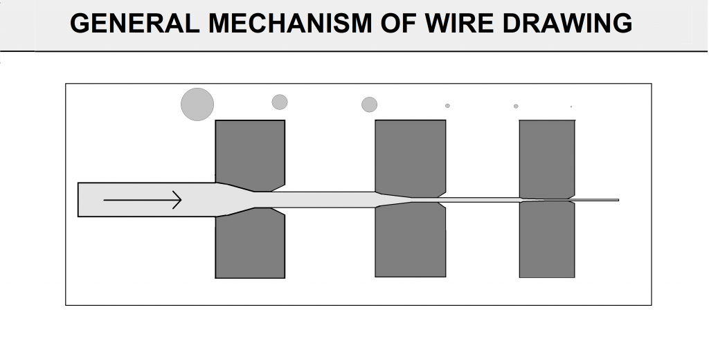
Drawing is a metal forming process used to reduce cross section and increase length of work piece. This process associated with tensile force which distinguishes it from other metal forming processes like extrusion, forging etc. In this process a large cross section work piece is forced to pass through a die which has smaller opening comparing cross section area of work piece. This will plastically deform the work piece by decreasing its cross section area and increases its length. This process is used for making wires, rods, tubes etc.(FigA4)
Fig A4
Raw Material for Welding Wire Manufacturing
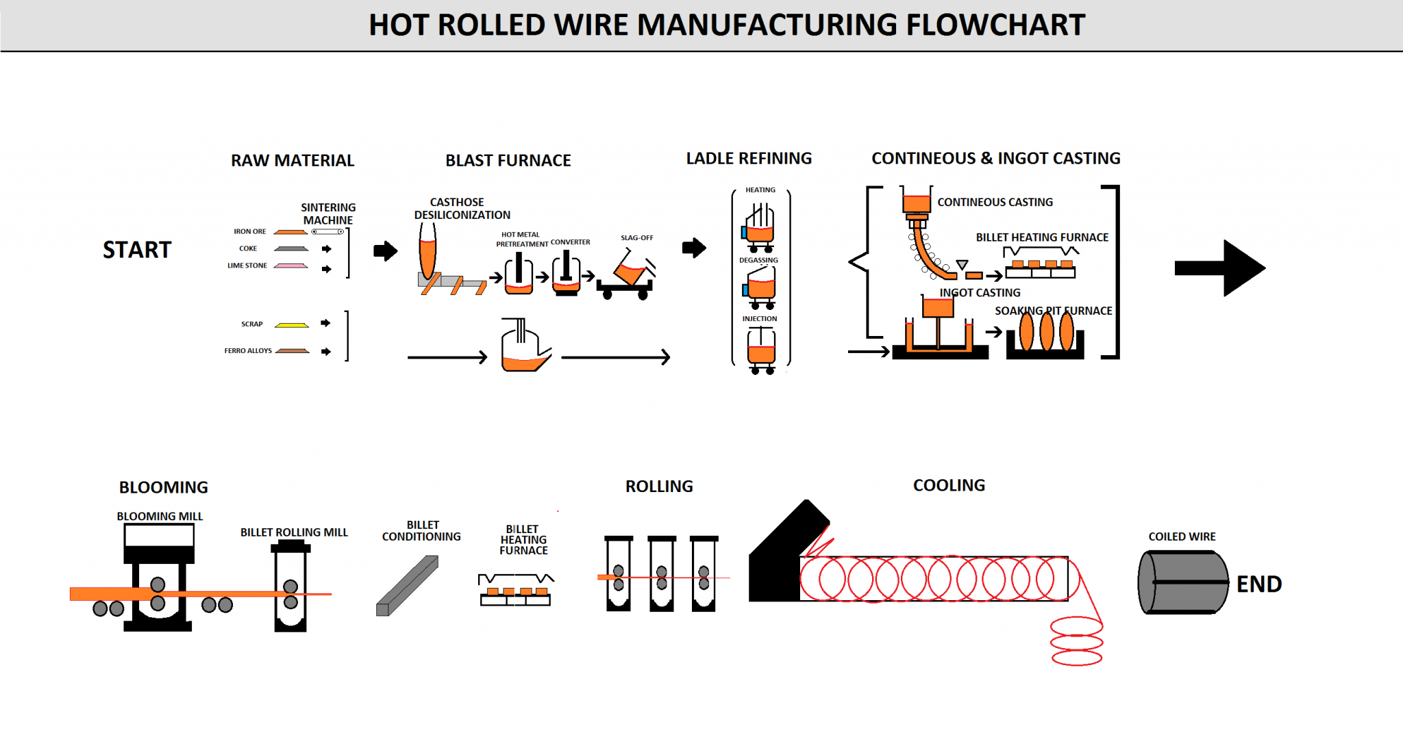
In the figure below ,the whole manufacturing process of hot rolled coiled wire is shown, this wire is used as a raw material for manufacturing of welding wire(FigB4).
The dust or other scale particle should clean from the rod before drawing. This process is done by acid pickling. the prepared skin is gone throw the drawing machine .
Fig B4
Important Items In Welding Wire Manufacturing
There are two important items in the of producing welding wire that need special attention:
1-Die
2-Lubricant
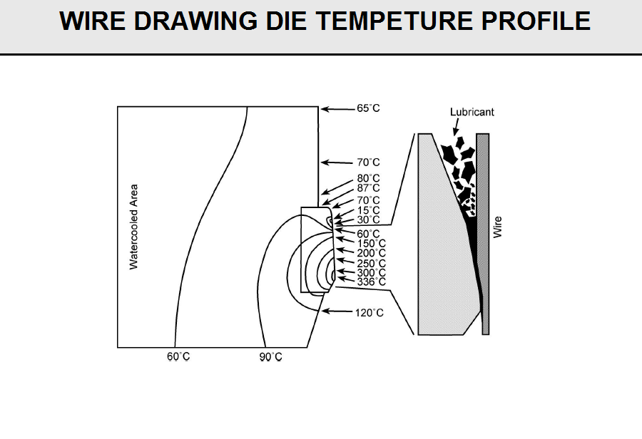
In the Wire drawing process,the wire is pulled through a series of drawing dies.The die is affected by several stresses so the die box should charge by different types of lubricant to increase the life of dies.
The wire drawing process reduces the size of a ferrous or non-ferrous rod down to a variety of finished sizes including super fine wire. This process is accomplished by passing the wire or wires through a series of single or multi-wire drawing machines. The drawing dies used in these machines can be Tungsten carbide, Natural Diamond or Synthetic Diamond, and the type of die utilized is choosen by the type of material being drawn. These tools are constantly under the high temperature condition because of wear between wire and dies (Fig D4)
Fig D4
Based on Manufacturing Method ,selection of dies should be consider .In wet wire drawing , all the wire draw dies are submerged in the lubricant and subsequent draws are taken in a compact machine of either 9, 11 or 13 dies. Where as in dry wire drawing, the die is placed in a die box which is filled will lubricant powder (FIG E4)
FIG E4
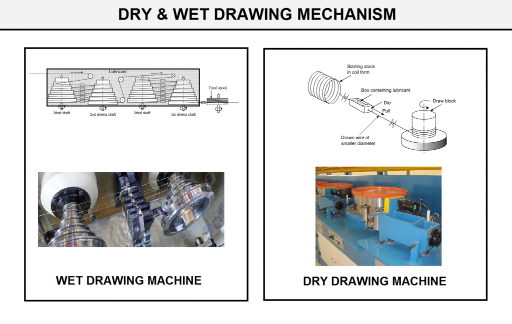
As mentioned before, Wire drawing manufacturing can be classified into two main methods: dry drawing and wet drawing. Generally, a straight line wire drawing machine is a kind of dry drawing machine, wire are not submersed in lubrication fluid. This drawing machine has good productivity due to higher drawing speeds with the twist-free operation. As a result of good cooling conditions, low torsion, less wire deviation, the finish wire has a good quality.
In contrast to dry drawing, wet wire drawing is notable for its wire, coil are soaked in lubrication liquid. This makes sure good lubrication condition and reduces friction force between the wire and equipment. It is ideal for drawing fine wires, ferrous or non-ferrous.
As mentioned before, There are various ways to produce different types of wires. In addition, welding wire manufacturing machines are constantly being updated. The following are two common methods of producing different types of welding wires with details of all the steps.
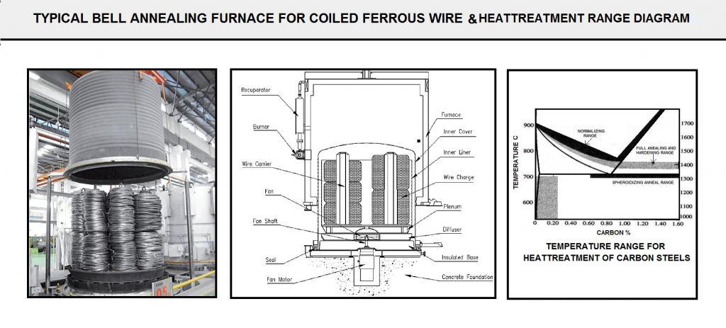
1) Annealing
Annealing is commonly heat treatment used to soften metal for cold working. During cold working, the metal can become hardened to the extent that nay more work will result in cracking. By annealing the metal beforehand, cold working can take place without any risk of cracking. That’s because annealing releases mechanical stresses.
For example for low carbon steel welding wire , this process involves heating of steel to a temperature just below the lower critical temperature (732.c) of steel for 2-6 hour depend on wire condition.
there are number of factors that must be carefully considered and controlled. One of the most important is the furnace atmosphere that surrounds the parts as they heat and cool.
(Figure A6) show the sample of annealing furnace for low carbon steels and diagram of annealing temperature based on carbon content.
Before starting the production process, the tensile test of the wire is performed. The high strength of the wire, which will be specified in the tensile test, will determine the need for annealing to reduce the strength and increase flexibility.
FIG A6
2) Pickling
Pickling is a process used in the metal working industry, in which acid is used to remove foreign substances from the metal surface. Pickling is a finishing process in which heavy oxide crust or scale is removed chemically. That is done by immersion in a bath, called pickle liquor, of suitable mixtures of acids. Scale develops on the surface of iron or strip steel, steel wire, and some other forms of steel, during hot forming or heat treating in air. The most used solution to treat Carbon steel products, with an alloy content less than or equal to 6%, contains either hydrochloric (HCl) or sulfuric acid (H2SO4). Hydrochloric acid is more expensive than sulfuric acid, but its action is much faster while minimizing base metal loss. It avoids the formation of smut and decreases the danger of excessive attacking.
The purpose of this process is to eliminate the surface oxides present on the wire surface to facilitate the drawing process and extend the life of the dies.
This process is accomplished by immersing the coils of wires in a immersion in a special solution path. Depending on the type of wire, the process steps, such as the number of paths and the type of acids, and how the surface will be neutralized after washing will vary (figure B6).
FIG B6
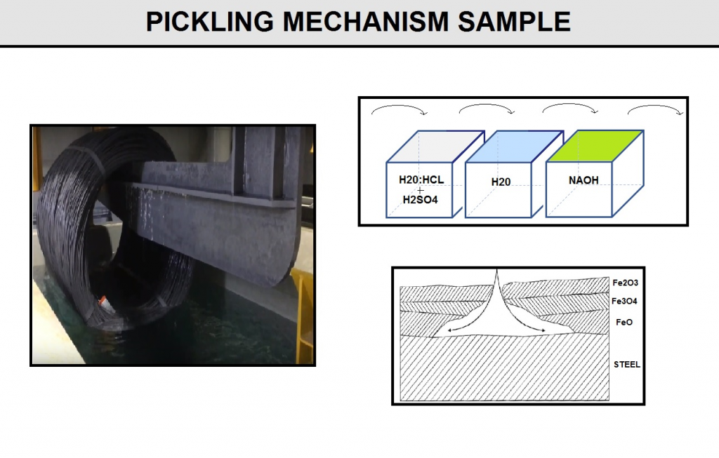
The specifications of the solutions poured into the path and the steps to be followed for the carbon steel wires can be as follows:
Stage1: At this stage, the coil is placed in a path containing 40% Hydrochloric acid and 60% sulfuric acid for 10 to 15 minute.
Stage2: At this stage, the coil is placed in a path containing water for 2 times in 5 minute.
Stage3: At this stage , the coil is placed in a path containing Sodium hydroxide at a concentration of 3%. This solution is used in the final stage of surface neutralization application.
3) Drawing Line for Welding Wire Manufacturing
3-1) Drawing Line: Dry Drawing Line In 2 Step (Thin End Product) (MIG/MAG & TIG Welding Wire)
Flow Chart A7
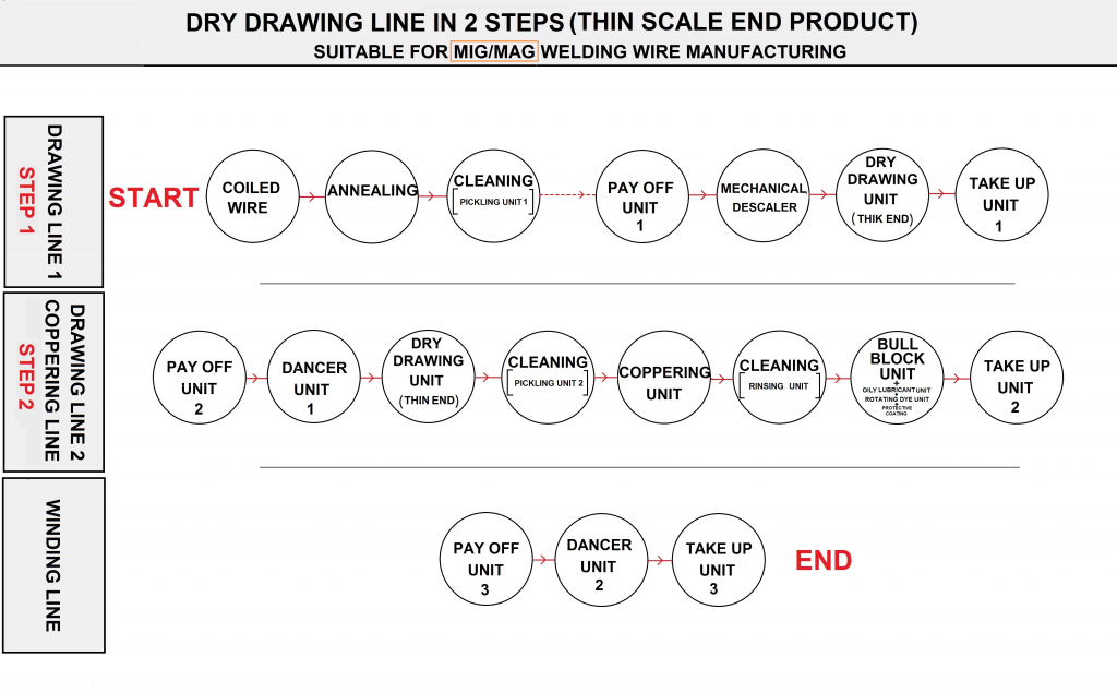
Flow Chart A7-1
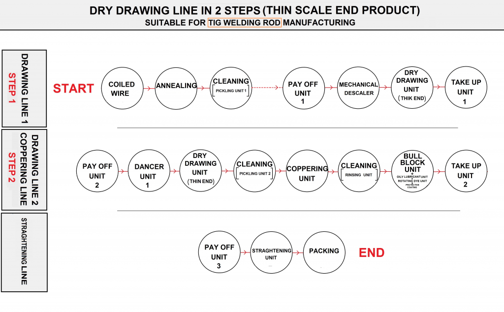
Table C6
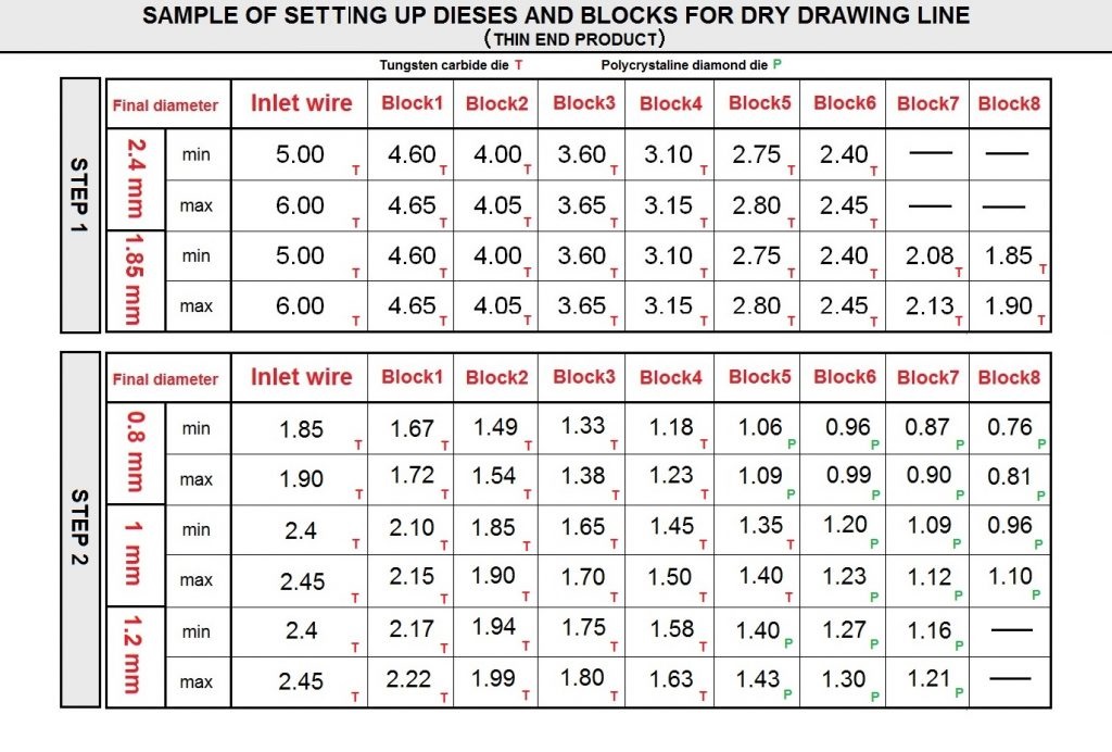
Based on flowcharts (A7&A7-1), the diameter of the primary wire will reach the desired final diameter in two stages and the copper plating will be performed on it.
In the first step, the goal is to reach the diameter of the primary wire, which is in the range of 5 to 6 mm, to a final diameter of 2-2.4 mm. This is possible by engineering the number of blocks and dies and the percentage of diameter reduction in each dies as shown in the (table C6).
In second step, the wire will charge to the line to reach the final diameter (table C6).
Different dies and lubricants have been used in stages due to the percentage of reduction area and tensile strength of wire in each block.
It should be noted that in the proposed method, all the lubricants used are dry powder type except at the last station that oily type is used before rotating die . Also used as the final coating prior to the last take up in step 2 , laloline natural animal oil is used as a skin pass. The final weight of the wheel that is welding wire wrapped around it is 800-1000 kgr.
Finally, in the final part of the production, the welding wire produced in the second step that is coiled on the wheel , will payoff and the machine will take it up to 15-20 kgr spool as a final product. And also for tig rod manufacturing the wire straightener is used after step 2 as a final production stage(FIG A7-1).The last stage is packing that is variable because of the packing method will divide in 100%seal condition or just resist again simple damage with shrink and cartoon.
3-2) Dry Drawing:Dry Drawing Line In 1 Step (Thick End Product) (SAW Welding Wire)
Generally for the production of welded wires with a diameter greater than 2.5mm , it is recommended to perform single step dry drawing method as shown in (flowchart B7).Welding wires in this diameter range are commonly used for submerged arc welding wires manufacturing.
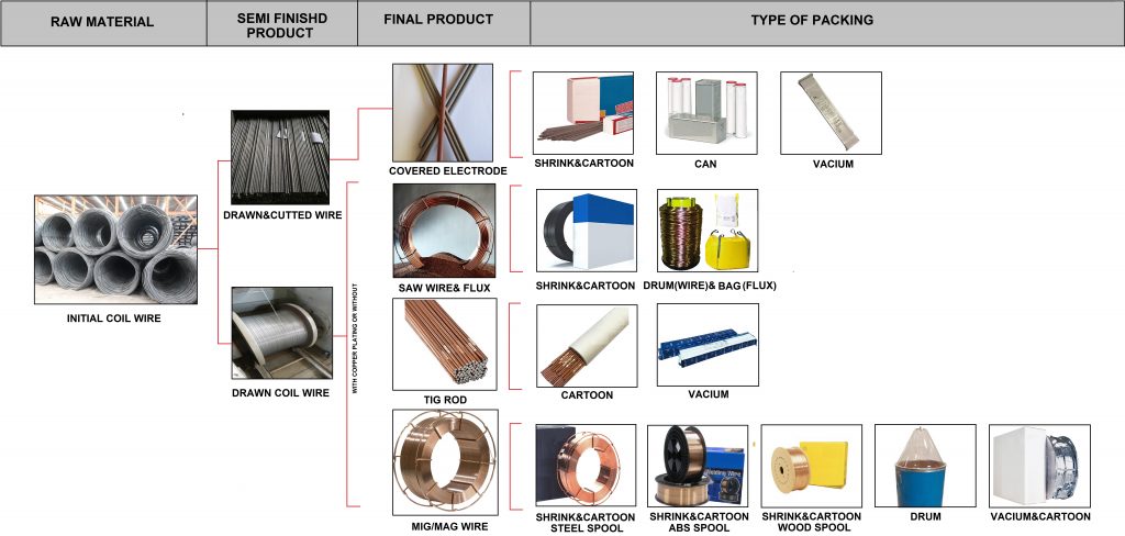
The procedure of production wires and types of packing based on each product in this method is shown in (FIG E6).
Flow Chart B7
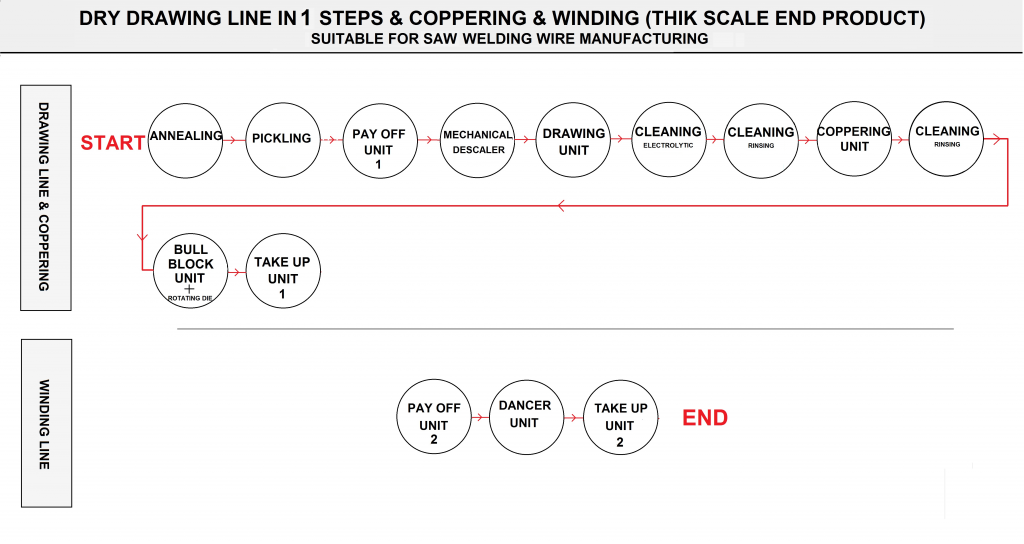
FIG E6
Important Points in This Process Are:
- Control the wire diameter at all stages according to the instructions as in (Table C6).
- Convenient drawing speed.
- Select the correct type of lubricant according to the die type and percentage of reduction area at each station and the drawing speed of machines.
- Ensure the proper number of rounds wrapped in each block before starting the drawing process.
- Ensure proper cooling of blocks and other parts by water cooling system equipment.
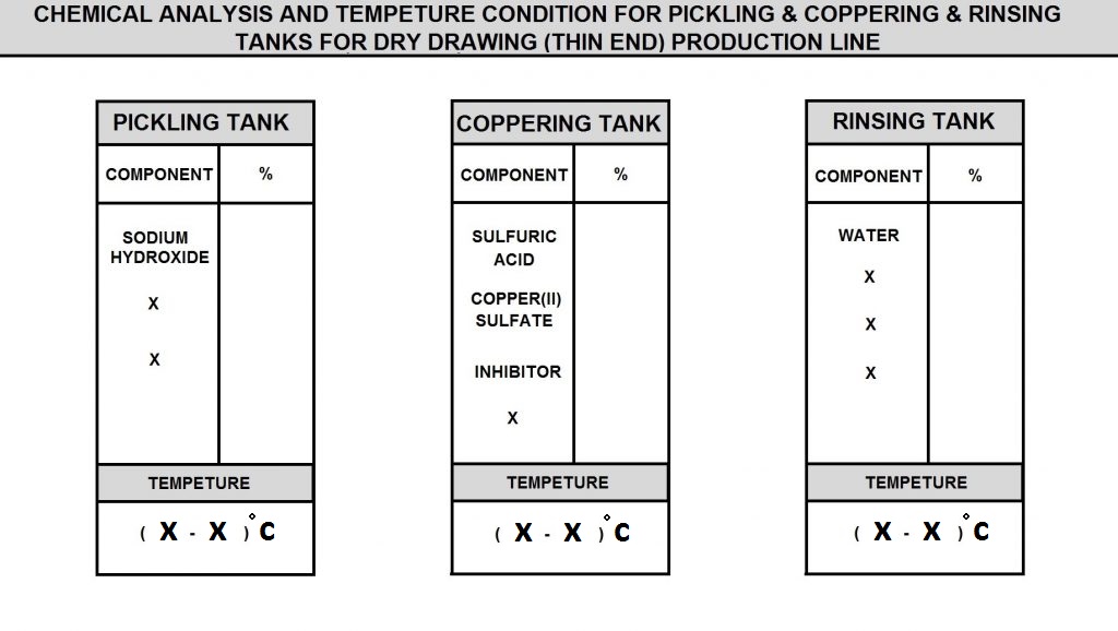
- Accuracy in the correct implementation of the instructions for the preparation of the tanks in the production line, including the order of addition of the chemicals and the amount of each and the knowledge of the methods of control and testing of these materials in accordance with the quality plan (FIG D6).
- All chemicals used in all stages of the production line, such as powder and oil lubricants and skin pass , and compounds used in (pickling, acid, rinsing) tanks are specially designed and these materials must be prepared according to their specs.
FIG D6
1) Annealing
The annealing of the wires for the production of MIG/MAG wires and TIG rods by the wet drawing process is the same like dry method.
2) Pickling
In this section, another pickling method used in the production of welding wire produced by the wet drawing is described .Similar to the previous method, this is done by immersing the coils in 3 soluble tanks. These stages are as follows:
2-1) Acid Tank
Pickling operations of wires are performed according to the instructions of each types of wires. At this point, the wire bundle inside the acid tanks Contains sulfuric acid at a controlled concentration and temperature, washed for a certain period of time. The status of acid baths including acid concentration and iron ion concentration is measured daily.
2-2) Rinsing
The wire is washed with cold water pressure after being removed from the acid bath for Remove the remain oxide layers. Then enter the water tank (PH=7) and immerse in the water for 1 minute. If the oxide shells are not removed or the black surface is observed the acid-wash operation is repeated again.
2-3) Borax Tank
At this stage, the washed wire should be immediately immersed in borax tank(with controlled concentration and temperature) for 2 to 5 minutes. In borax tank, while warming the wire, the borax material on the surface will precipitate.
After leaving the last tank, the wire should be at a temperature between 100-200 .c for 10-15 minutes in the hot air oven. The purpose of this work is the deposition of Borax on the wire surface.
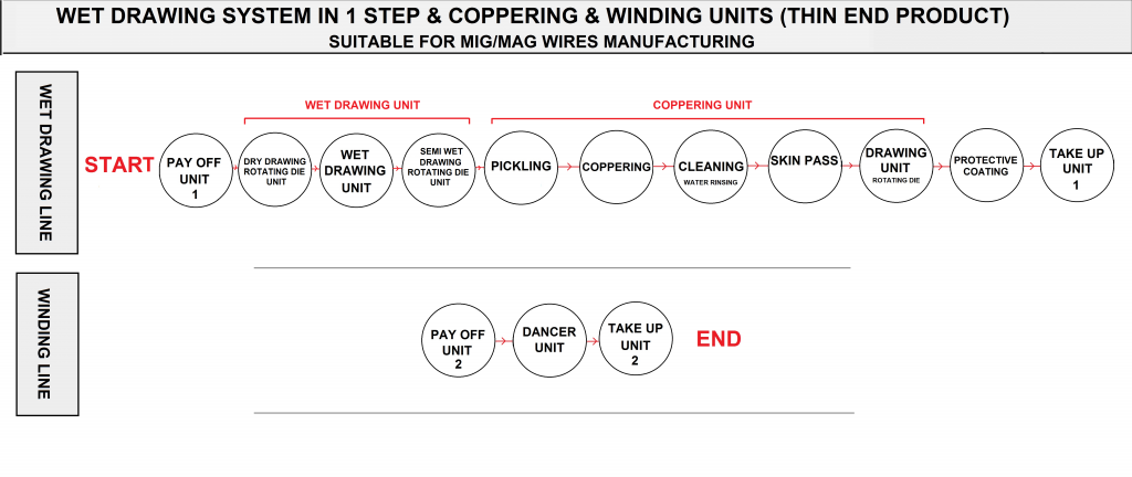
3) Wet Drawing Line In 1 Step (final dia:0.6-1.6mm) (MIG/MAG&TIG)
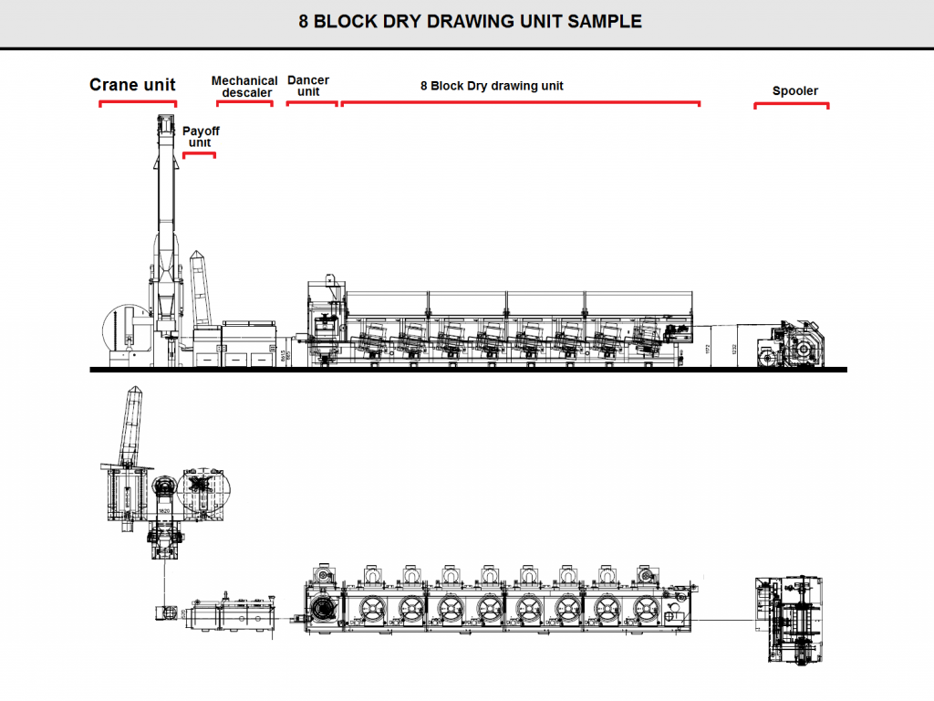
Generally for wire drawing with an initial diameter of 5 to 7 mm,the first stage is dry drawing.(FIG I6) is shown the layout design of the dry drawing machines .the wires that produced by this line will charge to the wet drawing line to achieve 1.6,1.2,1 mm as a final product.
FIG I6
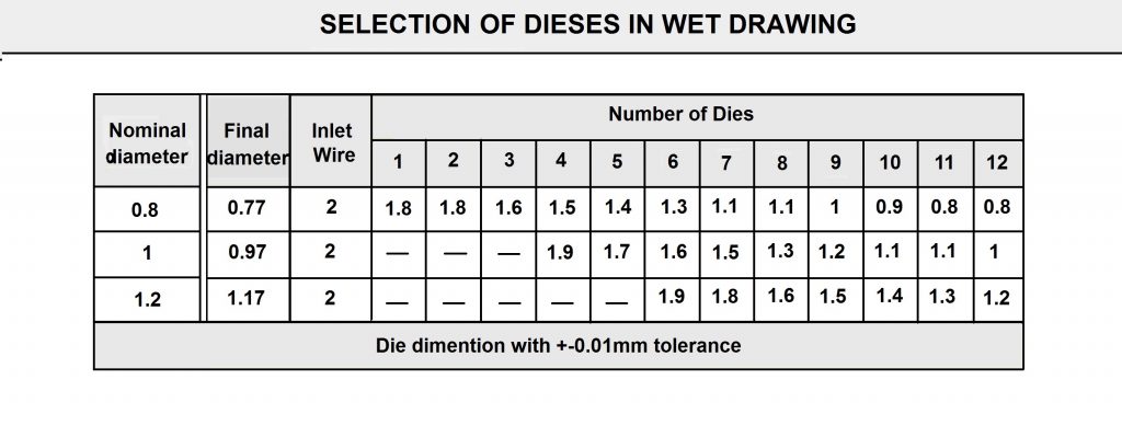
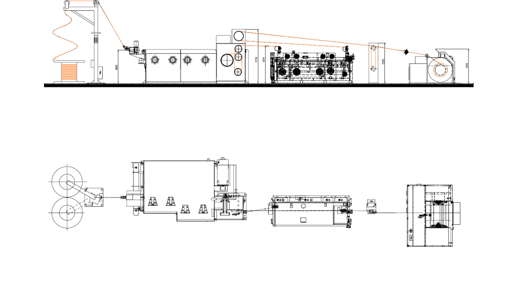
According to (Flowchart C7), the wet wire drawing procedure that are performed in one step is shown . Also The number of dies used to reach the final diameters is also shown in the (FIG F6).The layout of whole line is shown in (FIG G6).
Flow Chart C7
FlG F6
FlG G6
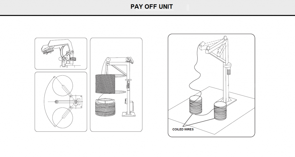
3-1) Pay Off Unit
The function of the machine is to unwind semi-finished metal wire from two coils in sequence and to continuously feed the wet drawing machine (FIG H6).
FlG H6
3-2) Wet Drawing Unit
The function of the machine is to draw to reduce the diameter of, metal wires.
The machine inlet wire must be made of low carbon steel, either crude or annealed, with a diameter ranging from 1.8 to 2.3 mm depending on the outlet wire diameter.
The Drawing Machine Consists of:
- a dry inlet die which reduces the diameter of the inlet wire by 10% to 30% depending on need;
- ten rotating dies inside the tank, divided between the two drawing cone units: each drawing step results in an average reduction in the wire diameter of 17.2%;
- an outlet rotating die which reduces the wire diameter by approximately 16%;
Note : four cone units, of which the second and fourth are equipped with cylindrical rings for drawing, while the first and third, each of which features a centring race, perform a transmission function.
The Machine’s Other Components Include:
- self-cooling a.c. motor equipped with encoder
- 3-phase power unit
- automatic stop device activated in the event of wire breakage;
- pedal control for jog operation
- drawing capstan which feeds the horizontal-axle coppering tank
- dancer for synchronization between capstan and tank;
- solenoid switch for safety guard closing
- rotating die for water-cooled first drawing
- drawing cones with ’Wolside’ coating
- heat exchanger for drawing bath cooling;
- belts for power transmission from the motor to the machine;
- recycle pump
3-3) Wet Drawing Unit Inlet Die
(Fig K6) shows the different parts of wet drawing unit. The first step of the drawing process, which takes place in a dry die, is the lubrication of the semi finished wire. This is done in case the said wire is not sufficiently lubricated following a previous dry drawing phase. The inlet die is equipped with a box which allows a special powder, usually made of calcium stearate, to be poured onto the metal wire. The inlet die is cooled using water only, which comes from an upper feeding line and is recycled. The cooling water must come from the mains supply and have a temperature of 5 to 25 °C.
FlG K6
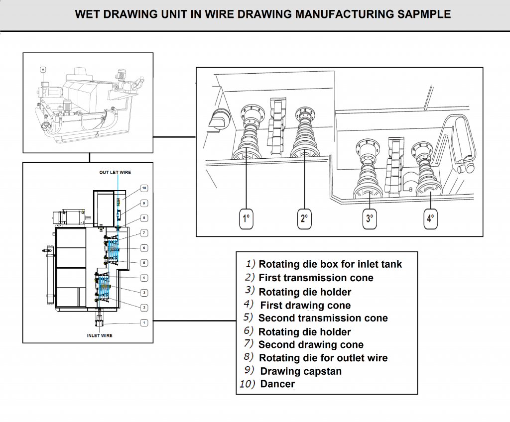
3-4) Wet Drawing Unit: Rotating Dies Inside the Tank
The dies inside the tank operate in a bath made of a water solution containing 3-4% vegetal oil. This solution reduces the friction between the metal wire drawn and the die. For this solution, the manufacturer recommends the use of major brand oils.
The solution cooling system is made of a oil/water heat exchanger. It is advisable to recycle water used by creating a closed circuit with a cooling tower.
The water and oil solution is pumped into the upper tank, called the drawing tank, by a pump with a submersible impeller located in the lower tank, where the solution collects when the upper tank is too full.
Nylon brushes are located at the inlet of the upper tank in order to prevent spurting.
When the machine starts working, the cooling circuit is disconnected; the solution is fed at room temperature and in about thirty minutes it reaches the recommended working temperature of about 45 °C. At this point, a bimetal mechanical thermostat connected to a solenoid valve switches on the cooling circuit consisting in an oil/water heat exchanger. If the cooling circuit does not work, the thermostat detects the fault by giving an on/off contact.If the bath temperature exceeds 50 °C, the bath loses its lubricating power.
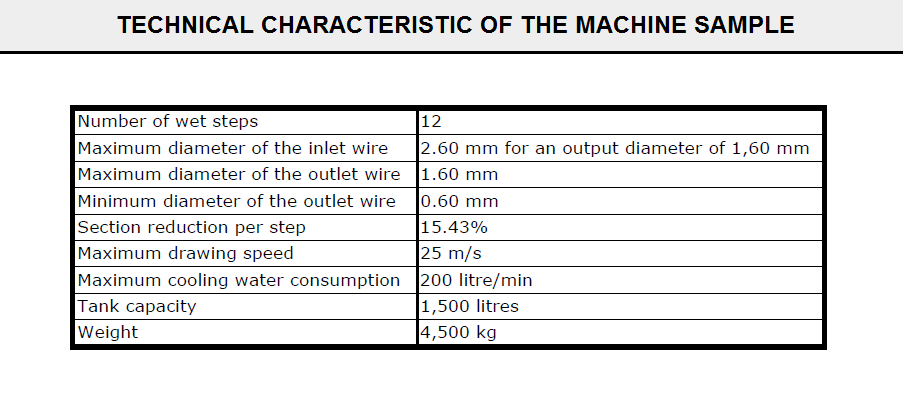
3-5) Wet Drawing Unit Out Let Die
This die is not operated in water and is lubricated by a jet of liquid lubricant which is fed along a supply line and sprayed out through a nozzle hidden behind the machine safety guards.(FIG J6) shows the sample of technical characteristic about this machine.
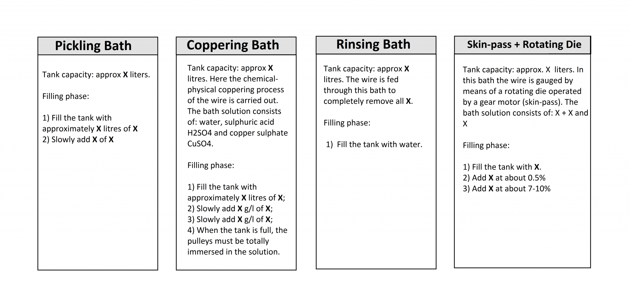
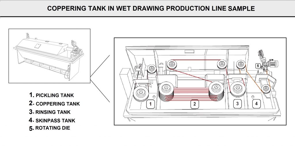
3-6) Coppering Unit
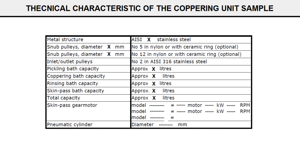
The function of the machine outlined in this manual is to copper plate the metal wire processed by the wet drawing machine and to gauge the wire by means of an additional skin-pass step in a rotating die.
The coppering tank consists of 4 sections (refer to Fig N6)
- Pickling bath
- Coppering bath
- Rinsing bath
- Skin-pass + Rotating die
The wire comes out of the drawing machine capstan, is fed into the pickling bath (1) or the coppering bath (2) depending on the pulley position follows a set course on snub pulleys and lastly returns to the drawing capstan or to the skin-pass pulling block. The coppering bath is a solution of sulphuric acid, copper sulphate and water. By means of a chemical physical process, copper is deposited onto the metal wire. The copper-coated wire emerges perfectly gauged from a rotating die called a skin-pass die, located in the last tank section (FIG M6) shows the technical characteristics of coppering unit.
FlG J6
FlG N6
FlG M6
3-7) Dancer
The function of the machine outlined in this manual is to synchronize the motor speed of the wet drawing machine and of the take-up to obtain optimal conditions for wire tensioning and sliding.
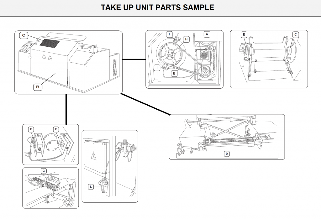
3-8) Take Up Unit
The function of the machine outlined in this manual is to wind the metal wire previously processed by the wet drawing machine onto reels with a diameter of 800 mm (DIN 46397).
The take-up consists of a rugged and compact structure made of welded steel elements.The base houses all the components of the machine, and includes:
- two closed side panels housing the mechanical units of the two spindles. There is one fixed and one movable spindle, and they are equipped with the reel supporting tailstocks.
- a central hollow compartment housing a platform to insert and position the reel; this platform is either fixed, enabling loading of reels with one diameter only (machine model ’without elevator’), or equipped with a lifting elevator, enabling loading of reels with different diameters (machine model ’with elevator’).
Refer to (Fig O6) concerning the machine model ’with elevator’The electric motor (A) transmits the motion to the fixed spindle (C) and to the wire traverse unit (D) by means of belts (B).
A pneumatic control locks the reel while the movable spindle (E) slides horizontally by means of two pneumatic cylinders (F).
The wire straightener (G) consists of two groups of rolls arranged on two orthogonal plates. Braking is applied by a large diameter disc brake (H) via two pneumatic calipers (I). The pneumatic system is equipped with the filter/reduction gear/lubricator unit (L).
FIG O6
Sample of Production Construction in Wet Drawing Procedure