Flux Cored Welding Wire Manufacturing
Introduction
This article is about the production of flux-cored welding wire. Read This Article about its quality testing.
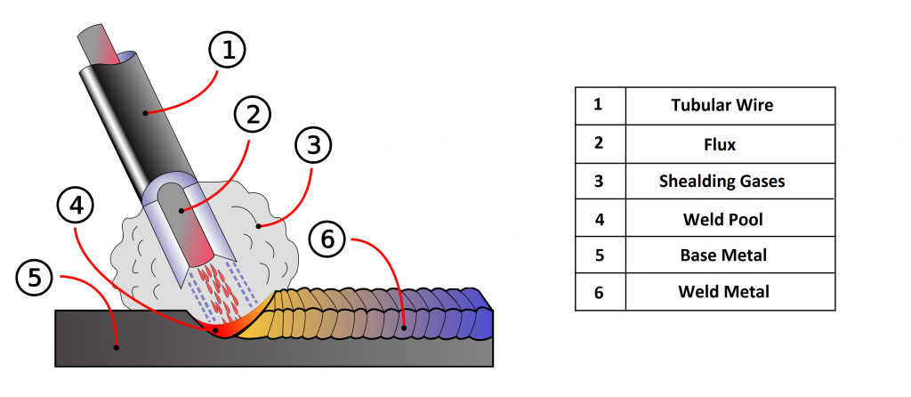
Flux-cored is an arc welding process that uses a tubular wire electrode with a flux-filled inner core. The American Welding Society calls this process “Flux Cored Arc Welding” or FCAW.
The first raw material of the Flux cored welding wire is the strip, the second one is a mixture of different powders that are placed inside the strip. Based on the production method and the physical structure of the product, this type of welding wire is divided into the two general types:
1-Seamed Wire
2-Seamless Wire
All flux cored welding is done on equipment that is similar to (and sometimes identical to) the equipment used in MIG or Gas Metal Arc Welding.
In flux cored welding, the wire electrode is fed through a wire feed unit. Usually, this wire feeder requires knurled rollers that can grip the tubular wire without flattening or damaging it. This is different from the smooth rollers used with solid MIG welding wire(FIG A9)
As in MIG welding, an electric arc forms between this wire electrode and the workpiece and heats both metals above their melting point. These metals mix together and solidify to join the workpieces into a single piece. The metal in the parts to be joined is called the “base metal” and the metal that comes from the melting wire electrode is called “filler metal.”Because the wire electrode melts as it is being used, the Flux Cored wire is called a “consumable electrode.” Flux cored welding always adds filler metal to the joint.
Difference Between Flux Cored, Metal Cored, and Solid Wire:
It would be complicated if we don’t know differences between some words and phrases like solid wire, metal-cored , flux-cored (self shield, gas shield):
Solid wire requires a shielding gas to protect the molten metal(GMAW).
Metal Cored wire is a tubular wire filled with metal oxides inside to make standard weld metal with defined chemical elements like nickel, molybdenum, manganese, etc. requiring a shielding gas.
Flux-cored gas shield wire also a tubular wire but filled with fluxing agents similar to flux on smaw electrodes may require an external shielding gas plus the gas produced from the wire’s flux (dual shield).
Flux-cored self-shielded creates enough shielding gas from the tubular wires flux and requires no external shielding gas. The shielding gas maybe 100% CO2 or a mixture of Argon with CO2 for steel welding.
Specification of Flux-Cored Wires Types
there are two main types of flux core arc welding: Self-shielded (known as FCAW-S) and Gas shielded (which is FCAW-G). In a self-shielded flux core, the weld is protected by the flux itself, and in a gas shielded flux core the shielding comes from a high-pressure cylinder. You need to be sure you are using wire in the way it was designed to be used because the chemistry behind these two processes is different.
Flux Cored electrodes that are designed to be self-shielded contain a flux that completely protects the molten weld pool. The flux in these electrodes creates a protective cloud that prevents gases like nitrogen and oxygen from reacting with the hot metal. One advantage of the self-shielded Flux core process is that the added cost and inconvenience of gas shielding equipment are eliminated. Also, self-shielded electrodes are less sensitive to drafts and breezes that easily contaminate gas-shielded processes like MIG welding. This can be a real advantage in some applications.
Electrodes designed to be gas-shielded rely on a secondary shielding gas to do the job of protecting the molten weld. The high-pressure gas cylinders used for this process are of the same design as those used in MIG and TIG welding. The cylinders contain gas under extremely high pressure, and a device called a regulator brings the gas to a useable pressure. One of the most common gases used to shield Flux core is pure CO2. Other gases, such as a CO2/Argon blends are also used, but one advantage of FCAW-G is that low cost CO2 can be used to shield the weld.
Another benefit of gas shielded flux core is the high deposition rate that can be achieved with the combination of flux and gas. Flux core -G has the ability to lay down metal at a really fast rate.
In both self-shielded and gas-shielded processes, the flux forms a thin layer of slag that protects the weld as it cools. This slag also helps the solidifying weld to take a consistent, low-profile shape.
In flux cored welding, all of the machine controls are set on the machine itself. The most important of these are polarity, wire speed and voltage. The trigger on the gun is just and on/off switch. For most flux core welding, the current is Direct Current or DC. DC is like the current flowing from a car battery. One wire is always the negative and one is always positive.
In self-shielded flux cored welding, the electrode is usually negative, and the workpiece is positive. The term DCEN is used for this, indicating that the current is DC, and the electrode is negative. You might also hear this called “straight polarity.”
In gas-shielded flux core welding, the electrode is usually positive, and the workpiece is negative. The term for this is DCEP, indicating that the current is DC, and the electrode is positive. This is also called “reverse polarity,” but DCEP is a more descriptive term.
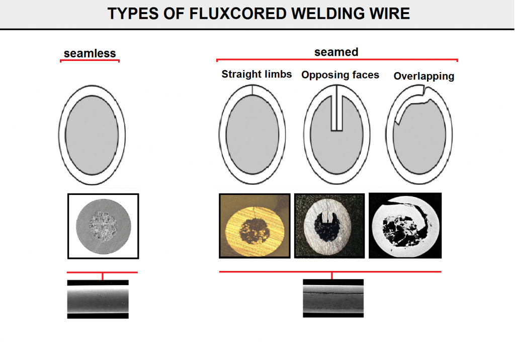
Flux-cored welding wire also can be classified by the geometric specification as shown in (Fig B9). Each type of these wires has its own production method and advantages and disadvantages.
Flux Cored Wires Typology
flux-cored wires can be classified by typology, wires of rutile, basic and metal-cored typology, or by productive technology, strip wires (or folded) or tubular (or seamless) wires. Concerning the classification by wire typology, the rutile-type wire is insuperable in applications under operational conditions (for instance in upright or overhead position) and it is highly appreciated for its high versatility and user friendliness; the metal-cored wire is mainly used to replace the solid wire and it is appreciated for its higher deposit levels whereas the basic wire is preferred in applications where are required high technical and mechanical performances, mainly with medium-high alloy steels. Referring instead to productive technologies, as we are going to explain more in detail, the folded wire is essentially preferred for its weldability specifications whereas the seamless wire for the impermeability and the superior sliding.
FIG B9
Ingredients in Core Wires
(figure G15) is shown the sample of formulation for types of flux cored welding wire. The composition of the powder in cored wires differs for different types of wires and it affects the welding characteristics and the metallurgical analysis of the weld metal. Wires can be optimized for a range of characteristics by varying the composition of the powder:
1-The addition of anti-oxidizing elements such as manganese or silicon refines the weld metal.
2-Slag-forming elements are added in order to protect the weld while it is solidifying, to control the shape of the weld metal and to improve positional welding performance.
3-Arc-stabilising additives produce a stable, spatter-free arc.
4-Alloying elements such as nickel, chromium, molybdenum and manganese can be incorporated in the powder in order to modify the mechanical and metallurgical properties of the weld.
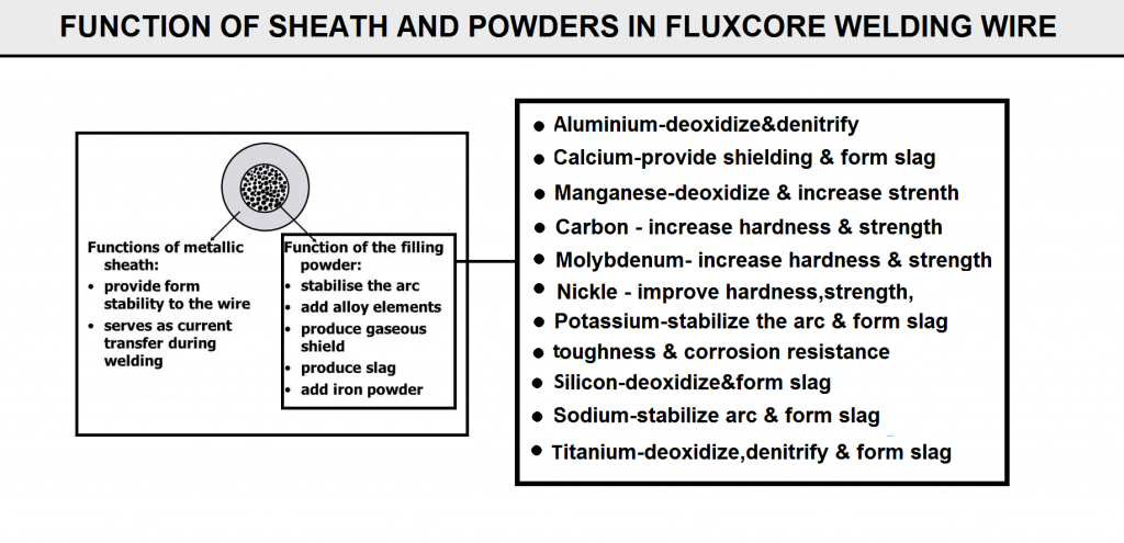
(FIG C9) shows the functions of sheath and powders in flux core welding.
FIG G15
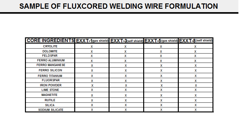
FIG C9
Strip Used in FCAW Wire Production
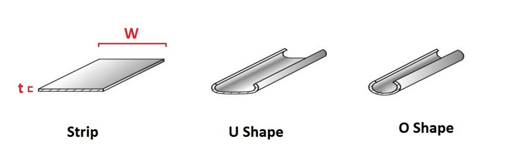
The strip is the raw material of production in fcaw wires. During the various manufacturing processes, the primary strip is first formed into the u shape and then formed to O shape to close the seam by different methods (FIG A15).
In this case, the ratio t/W of the thickness t of the band steel to the width W of the band steel is preferably set within a range of 0.06 to 0.12. The board thickness t and the width W of the band steel (hoop) are naturally determined by the wire diameter of the product FCW. However, according to the findings of the inventors, the ratio t/W also affects the low hydrogen content characteristic of the FCW. Namely, when the t/W is less than 0.06, and too small, the band steel or the wire becomes unable to hold Such a Strength as to withstand forming or wire drawing with the flux filled therein. This facilitates the occurrence of break age. For this reason, the forming or wire drawing Speed. particularly the moisture content in the atmosphere in the wire drawing Step to a trace amount according to the environment for the production of the FCW, there is a high possibility that the amount of moisture absorbed by the wire (flux) during wire drawing increases to Such a degree as to cause welding defects. Further, the wire feedability is also reduced.
FIG A15
Lubricant Consideration in FCAW Production
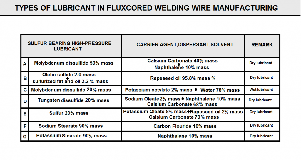
Various compounds are used as lubricants in the welding wire manufacturing process.The components of these materials can be divided into two parts: sulfur bearing high pressure lubricant and second part as carrier agent ,dispersant or solvent.(FIG H9).
The high-pressure lubricant denotes a lubricant having a property of forming the shape of a film even under high pressure.The term “Sulfur-bearing denotes “consisting of a Substance containing a Sulfur atom. lubricant, but containing other high-pressure lubricants Such as Soaps of an alkali metal type typified by Sodium Stearate and an alkaline earth metal type, carbon fluoride, TEFRON (registered trademark), and boron nitride, and the wet lubricants are inferior in lubricating performances as compared with the wire drawing lubricants containing a Sulfur-bearing high-pressure lubricant of the present invention. For this reason, when wire drawing is carried out at a higher speed, particularly, it becomes necessary to use a wire drawing lubricant in a large amount. As a result, it becomes very difficult to carry out Substantial removal of the lubricant by a physical means Such as wiping off of the oil lubricant from the Surface of the wire running in an in-line state after wire drawing. Further, the lubricant tends to remain on the wire Surface, which causes arc instability during welding, and results in a hydrogen Source causing welding defects due to porosities.
In contrast, the wire drawing lubricant containing a Sulfur-bearing high-pressure lubricant of the present invention is excellent in lubricating performances. Therefore, even when wire drawing is carried out at a higher Speed, only a Small amount of the wire drawing lubricant is required to be used. When the amount is expressed as the amount of the lubricant deposited in terms of the Sulfur amount on the wire Surface after wire drawing, the residual amount of the lubricant on the wire Surface after wire drawing is about 0.1 to 0.6 g per 10 kg of the wire. With Such a degree of the lubricant residual amount, it is possible to carry out the following and Subsequent Step of removing the lubricant by a physical means in conjunction with high Speed wire drawing continuously through an in-line process, and at a high Speed.
The dry type wire drawing lubricants containing a Sulfur-bearing high-pressure lubricant include molybdenum disulfide, tungsten disulfide, Zinc Sulfide, and the like. Alter natively, it may also be a dry type wire drawing lubricant containing the Sulfur-bearing high pressure Solid as a main component, and an additive Such as a carrier agent including naphthalene, titanium oxide, mica, graphite, calcium carbonate, calcium fluoride, or the like added thereto.
The dry type lubricant denotes not being a wet lubricant containing liquid water or oil component. What material is used as the lubricant affects the amount of moisture absorbed in the whole wire. Therefore, it is desirable in the present invention that the Sulfur-bearing high pressure lubricant itself is of a dry type.
Alternatively, it may also be a semi-wet type wire drawing lubricant prepared by further adding a Small amountof an oil solvent Such as polyisobutene (Synthetic oil), or A rapeseed oil (vegetable oil) to the dry type wire drawing lubricant.
The preferred composition range of the wire drawing lubricant for the acquirement of excellence particularly in lubricating performance, the increase in the wire drawing Speed, the reduction in the hydrogen content of the wire, and the removal in the in-line process is as follows: one, or two or more Sulfur-bearing metal compounds Such as molybdenum disulfide, tungsten disulfide, and zinc sulfide, 20 to 80 mass %; the one, or two or more carrier agents, 40 to 50 mass %; and the one or two or more oil solvents, 5 to 40 mass %. Further, when a Small amount of a metal Soap is further added thereto, it is possible to improve the wire drawing productivity.
In addition, the one containing a sulfur-bearing high-pressure lubricant in a form dispersed or dissolved, if required, with the carrier agent or the like, in a Solvent Such as water, an animal or vegetable oil, a mineral oil, or a Synthetic oil is appropriately used within Such a range as to Satisfy the required characteristics as the wire drawing Examples of the Sulfur-bearing high-pressure lubricant include Sulfur-bearing metal compounds Such as molybdenum disulfide, tungsten disulfide, and Zinc Sulfide, and Sulfur-bearing Synthetic oils Such as olefin Sulfide and Sulfurized fats and oils. Examples of the Solvent include water, animal and vegetable oils (such as palm oil, rapeseed oil, coconut oil, and castor oil), mineral oils (such as machine oil, turbine oil, and spindle oil), and Synthetic oils (Such as hydrocarbon type, ester type, polyglycol type, polyphenol type, Silicone type, and fluorine type). However, these are also preferably Selected from non-hydrogen-bearing com pounds as much as possible. The preferred composition range is as follows: a Sulfur-bearing lubricant in the range of 20 to 80 mass %; a carrier agent in the range of 40 to 50 mass%; and a solvent in the range of 5 to 40 mass %.
FIG H9
Method for Production of Seamed Carbon Steel Fluxcored Wire (Final diameter: 0.8-1.6)
FIG E9
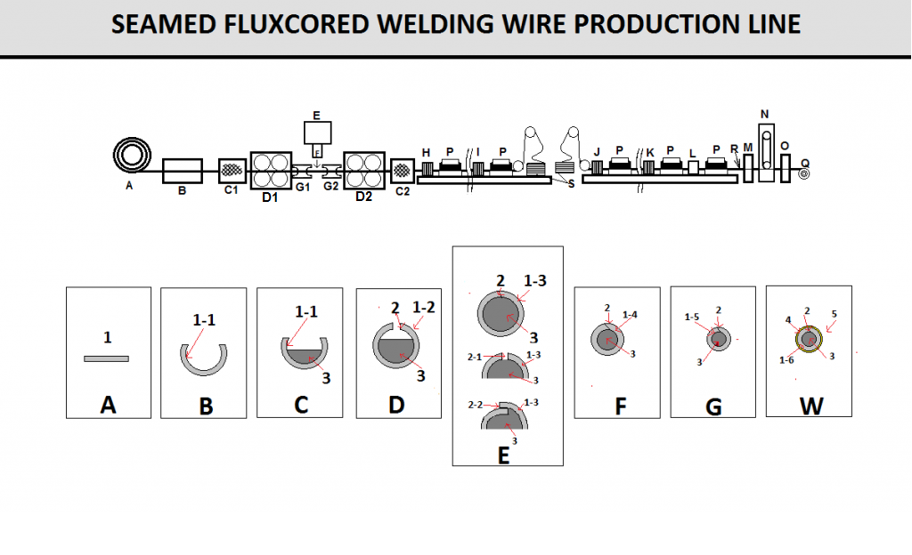
FIG J9

1) Uncoiling and Cleaning (Degreasing) Step
In (FIG E9), a coil-like band steel A uncoiled by an un coiler, first, cleaned and degreased in advance by a cleaning and degreasing Step B. The working oil and contamination attached on the Surface when a broad material Steel sheet was Slitted along the direction of width into the narrow band steel A are removed by the cleaning and degreasing Step B. Even a Small amount of the working oil attached on the surface of the band steel A may result in a hydrogen Source causing arc instability during welding and welding defects Such as porosities. Therefore, the cleaning and degreasing Step B are preferably carried out.
2) Lubricating
After cleaning unit, the band steel A will insert in a lubricant coating step C1.this unit will help the strip to be formed more comfort in next step.
3) Forming Into U Shape
The band steel A thus coated with the lubricant is formed from its planar cross sectional shape shown in (FIGE9) into a band steel1-1 which is U-shaped in cross section. The forming roller row (group) D1 shown in (FIG E9) shows an example in which two forming rollers are arranged in Series. The number of the forming rollers to be arranged in the forming Step is appropriately Selected according to the forming conditions Such as the width, thickness, or hardness of the band Steel A.
4) Flux Filling
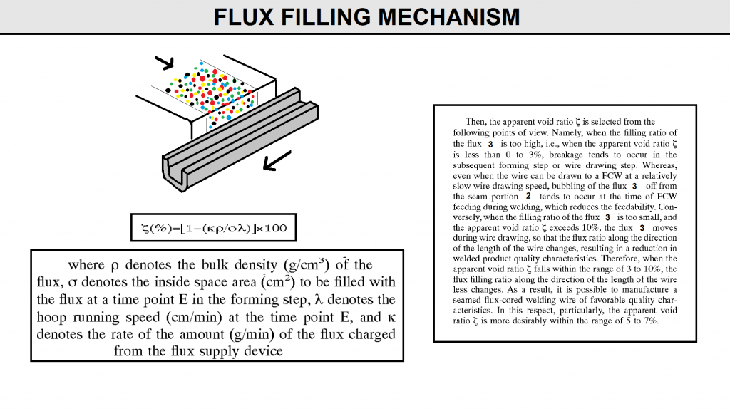
The band steel 1-1 formed in a U shape in cross section then receives a flux 3 from a flux supply device E. Thus, as indicated with, the flux 3 is filled (included) in the U-shaped space of the band steel1-1 with a given inside filling ratio (void ratio) ensured. The usable flux supply device E is a belt feeder, a smooth auto feeder, a table feeder, a Syntron feeder, or the like. The filling ratio (apparent void ratio:₰ ) of the flux3 into the U-shaped formed band steel 1-1 is expressed as the following equation (FIG F9).
Whereas, the moisture of the flux 3 to be supplied to the U-shaped formed band steel 1-1 is preferably dried (heated at 110° C. to 250° C) during Supply over the flux supply device E before supply (inclusion) to previously control the moisture content in the flux within the range of 500 ppm or less. Alternatively, the flux may also be previously dried in an off-line process (preliminary batch processing).
However, in order to minimize the number of manufacturing Steps, the process in which drying is carried out over the flux supply device E is preferably adopted as means for removing the moisture through the in-line process. Specifically, heating is carried out by a heater or the like in a flux Supply path (passage) of the flux Supply device E. Further, if possible, it is also effective that the whole manufacturing line (factory) for the FCW is air-conditioned at a relative humidity of 70% or less, and more preferably60% or less.
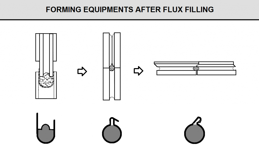
U-shape formed band steel 1-1 thus filled with the flux 3 is then further formed into a tube-like wire1-2 indicated with D of (FIG E9) by a forming roller row D2. The conditions for the forming roller row D2 are the same as with the forming roller row D1.
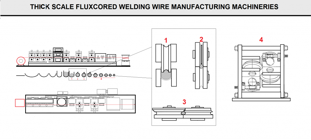
The tube-like wire 1-2 has a gap portion equal Seam 2 at which the opposite ends along the direction of width of the band steel is close to each other over the direction of length of the wire 1-2. The seam2 still exists as the gap portion even when the wire 1-2 has been reduced in diameter to be a wire 1-3, and a wire 1-4 through the subsequent wire drawing step. Specifically, even when the wire 1-3 has a cross section 2-1 of a butt type, indicated on an enlarged Scale with an extension line from the wire 1-3, and the opposite ends along the direction of width of the band steel are butted, the Seam 2 exists. Alternatively, as another embodiment, even when the wire 1-3 has a cross section 2-2 of lap type, Similarly indicated on an enlarged Scale with an extension line from the wire 1-3 and the opposite ends along the direction of width of the band steel overlap each other, the seam 2 exists. This also holds for a product FCAW.
FIG F9
An example of the forming equipment after flux filling is shown below
5) Wire Drawing Lubrication
The formed tube-like wire 1-2 is then coated with the lubricant of the present invention on the surface of the wire 1-2 in a lubricant coating step C2, followed by wire drawing. The lubricant may be either the same as, or different from the lubricant in the coating step C1 so long as it falls within the Scope of the present invention. Herein, the lubricant coating steps may be not only set at C2 before wire drawing, but also set appropriately during the wire drawing Step according to the wire drawing conditions. At this Step, the amount of the lubricant to be deposited on the surface of the wire 1-2 to be drawn is preferably set to be the residual amount within a range of 0.1 to 0.6 g per 10 kg of the wire, including the amount of the lubricant which has been previously applied in the lubricant coating Step C1, and remains on the Surface of the wire C1 in terms of the amount of Sulfur on the wire Surface after drawing in the wire 1-5 or in the wire R after completion of wire drawing.
When the residual amount of the lubricant deposited is less than 0.1 g in terms of the Sulfur amount, the lubrication becomes insufficient for high-Speed wire drawing.
As a result, the wire to be drawn becomes more likely to undergo burning or breakage. On the other hand, when the residual amount of the lubricant deposited exceeds 0.6 g in terms of the Sulfur amount, the exceSS amount of the lubricant is unnecessary from the Viewpoints of forming and wire drawing lubrication, and it becomes difficult to carry out the removal of the lubricant by the following and Subsequent physical means continuously in conjunction with high-Speed wire drawing at high Speed. Therefore, the lubricant becomes more likely to remain on the FCW Surface, which inhibits the arc Stability during welding.
6) Wire Drawing With Roller Die
The wire drawing step of can be broadly divided into a primary wire drawing Step and a Secondary wire drawing Step. With the wire drawing Step, the wire is reduced in diameter to the product diameter or a wire diameter close to the product diameter. Herein, as indicated with E and F of (FIG E9), the wire is reduced in diameter from the wire 1-3 to the wire 1-4 by the primary wire drawing. Further, as indicated with F and G of (FIG E9) the wire is reduced in diameter from the wire 1-4 to the wire 1-5 of the product diameter by the secondary wire drawing. The wire drawing step of (FIG E9) shows an embodiment in which the primary wire drawing Step and the Secondary wire drawing Step are carried out Separately from each other. Thus, whether the wire drawing Step is divided, or the primary wire drawing Step and the Secondary wire drawing Step are carried out continuously through the same process to draw the wire to the product diameter is appropriately Selected according to the design conditions of the band steel, the design conditions of the product FCW, the productivity, or the like. Further, a plurality of lines of the Secondary wire drawing steps (C) may be set per line of the primary wire drawing step (B). Alternatively, one line of the Secondary wire drawing step (C) may also be set per a plurality of the primary wire drawing steps (B). Either the former Setting or the latter Setting may be appropriately Selected according to the productivity balance between the primary wire drawing and the Secondary wire drawing.
For the primary wire drawing step, roller die rows(groups) H to I made of Super hard materials are arranged in multiple stages (6 stages or 6 groups in the example of FIG E9). For the Secondary wire drawing step, roller die rows (groups) J to K made of Super hard materials are arranged in multiple stages (5 stages or 5 groups in the example of (FIG E9). The number of the multiple stages of the roller die rows to be arranged is also appropriately Selected according to the wire drawing conditions. The primary wire drawing step of (FIG E9) is continuous to the forming Step in an in-line manner. Then, the wire after the primary wire drawing is once wound around a coil S. Further, as shown in (FIG E9), the wire around the coil S is uncoiled to carry out the secondary wire drawing Step.
The secondary wire drawing step is continuously followed by the lubricant physical removing means (steps) M+N, and the oil coating means O in an in-line manner. Alternatively, a skin pass finishing wire drawing Step by a hole die L may also be inserted prior to the wire drawing lubricant coating Step.
In the present invention, the steps subsequent to the wire drawing by roller dies, Such as the finishing wire drawing step L, the lubricant removing steps M+N, and the oil coating Step O are carried out through an in-line process (continuously through the same line). When these Steps are carried out Separately through an off-line processing, the productivity and the production efficiency of the overall product FCW manufacturing proceSS are remarkably reduced. This largely impairs the advantages of the increase in wire drawing Speed by the roller die group.
In the secondary wire drawing step, the oil-coated product FCW is wound into a coiler as Q. In addition, it is further rewound into a wire Spool, or charged into a pail pack through a step not shown. In the wire drawing step of (FIG E9), a reference numeral P denotes a capstan. Each capstan P is disposed at the Subsequent Stage of each roller die row.
Thus, it smoothly guides the wire to be drawn, thereby to ensure continuous high-speed wire drawing. The hole die L is provided in order to carry out the skin pass finishing wire drawing for improving the shape accuracy Such as the roundness, which is Selectively performed. The finishing wire drawing by the hole die L is intended for the wire drawn by roller dies from the tube-like formed wire to the wire diameter immediately preceding to the product diameter. The wire diameter immediately preceding to the product diameter denotes the diameter of the wire drawn in an area ratio of 1.1 or leSS relative to the product wire taken as 1. Alternatively, the finishing wire drawing by the hole die may also be applied to the Stage during wire drawing by a plural Stages of roller dies. In this case, the final Step of a Series of the wire drawing StepS is the wire drawing by roller dies.
Herein, the shape accuracy (such as roundness) of the product-diameter wire affects the wire feedability. In addition, it also largely affects the workability in rewinding the FCW 5 in the wire Spool, or charging it in a pail back in a separate Step. For this reason, the wire drawn by the roller die rows is preferably Subjected to finishing wire drawing by the hole die L finally. The wire drawing speed of the hole die is lower than with the roller dies. However, with Such a Secondary wire drawing line configuration, the high Seed performance and the continuity of the wire drawing Steps and the overall FCW manufacturing process will not be affected even when finish wire drawing is carried out by means of the hole die finally. When the finish wire drawing is carried out by means of the hole die, the wire drawn by the roller die row has a wire diameter close to the product diameter, and the wire after hole die finishing wire drawing has a final product diameter. In the present invention, the wire drawn by roller dies may have the final product diameter or the wire diameter close to the product diameter, i.e. a different diameter according to whether it has under gone hole die finishing drawing or not. The wire diameters resulting from wire drawing by means of the roller dies are generically referred to as roughly a product diameter.
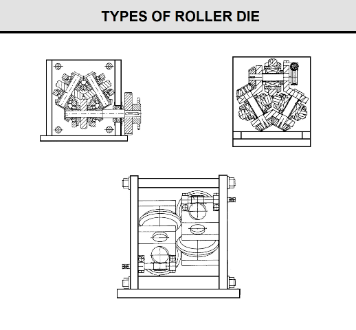
You can see also the essential parts of rollers in (Fig G9) a front view of a wire drawing device of a preferred embodiment. a front view on an enlarged Scale of an essential part of a roller die in the wire drawing device.
a front view showing a roller die wire drawing device row for use in wire drawing. Incidentally, the embodiment of the preferred basic configuration of the roller die wire drawing device is based on the increase in rigidity of a framework body Supporting the roller die.
FIG G9
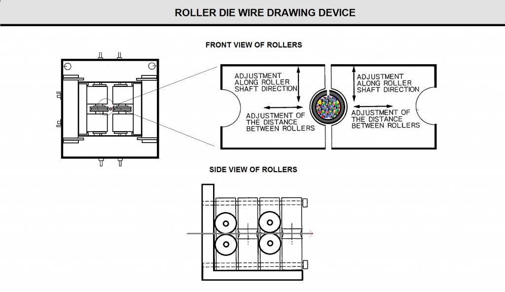
FIG Z15
7) Lubricant Removing Means
The drawn wire 1-5 is then subjected to removal of the lubricant from the wire surface by the physical removing means M+N. The lubricant removing means in (FIG E9) is intended for the three-stage in-line lubricant removal by the lubricant removing means M (indicated with a Small box) for Surface polishing and striking the wire at the preceding Stage, and the lubricant removing means N (indicated with a box in which a roll is shown) by a wiper roll at the Succeeding Stage. The lubricant removing means M for Surface polishing and Striking the wire is means for Surface polishing the running wire, and then, for example, causing a light-Weight piece to drop on a running wire, and to Strike the wire, and thereby removing the lubricant from the wire Surface. Whereas, the lubricant removing means N by the wiper roll at the succeeding Stage is means for removing the lubricant from the wire surface by the wiper roll provided with a felt for wiping off the lubricant on the Surface.
In addition, the in-line lubricant removal may be carried out in the following manner. Namely, the lubricant may be removed by another physical removing means Such as Shaking of the wire, or the appropriate combination of these physical removing means.
When the lubricant has not been removed, and has remained on the wire or the FCW Surface, the arc stability during welding is reduced, and welding defects are caused. Incidentally, in addition to the physical removing means for removing the lubricant, for example, an in-line Step of spraying 40+10 C. warm water on the wire surface, or dipping the wire in warm water or hot water, and removing the lubricant by cleaning may also added, if required, at the preceding Stage or at the Succeeding Stage of the physical removing means. However, for the dipping and cleaning, moisture tends to enter into the wire through the Seam portion.
Therefore, in order to remove this, preferably, the wire is passed through an in-line induction heating coil, So that the wire is heated by a high frequency electromagnetic induction current to reduce the total moisture content of the wire.
In the present invention, by using the wire drawing lubricant containing the Sulfur-bearing high-pressure lubricant as the lubricant for the forming and drawing Steps, the lubricant becomes more likely to be removed from the wire Surface by the physical removing means even without using the chemical lubricant removing means Such as a cleaning agent. As a result, the removal of the lubricant by the physical means can be carried out in conjunction with the high-speed wire drawing of the preceding Stage continuously and at a high Speed. AS described above, when other lubricants are used, the removing efficiency from the wire Surface is largely reduced, and the necessity of using a chemical lubricant removing means is caused. Accordingly, it becomes difficult to carry out the manufacturing of the FCW continuously and at a high speed in conjunction with the preceding-stage high-Speed wire drawing.
8) OIL Coating Means
The wire 1-5 from the surface of which the lubricant has been removed is Subsequently coated on the wire Surface with a lubricant 3 Such as a lubricant for improving the wire feedability by the oil coating means o as indicated with W of FIGE9. resulting in a FCW product. Herein, the oil coating means o is required to coat a small amount of a lubricant uniformly and for a short time on the Surface of the wire being carried (moving) at a high speed as shown in (FIG E9) To this end, use of a forced oil coating means Such as electroStatic oil coating is preferred from the viewpoint of the total hydrogen control of the wire. How ever, a process in which a felt impregnated with the lubricant3 is brought in contact with the wire for coating is generally adopted.
You can see also the essential parts of rollers in (Fig G9) a front view of a wire drawing device of a preferred embodiment. a front view on an enlarged Scale of an essential part of a roller die in the wire drawing device.
a front view showing a roller die wire drawing device row for use in wire drawing. Incidentally, the embodiment of the preferred basic configuration of the roller die wire drawing device is based on the increase in rigidity of a framework body Supporting the roller die.
9) Spooling for Packing as a Final Product
At the last stage of the production process, Welding wire produced and winds in large scale spool will uncoil by means of winding machine will coil in small scale spool as a final product.
Method for Production Seamed Carbon Steel Fluxcored Wire (Final diameter: 6-20 mm)
The invention (FIG K9) relates to a method of manufacturing a flux-cored wire in a metal sheath, seam by seam, used primarily for out-of-furnace treatment of steel and cast iron. Profiling U-shaped trough produce consistently for four passes in a horizontal mill, installed in front of the dispenser, the formation of a tubular workpiece and the weld seam is sequentially carried out for four passes in driving vertical and horizontal stands behind sealing the crate in which the compaction of the powder into the groove in the rolling stands of the upper roller.
In felling made oval brook radius equal to the radius of the formed tubular workpiece. The combination of a tubular piece with a seam seam produce sequential deformation in the two drive and two non-driven three-roll stands. Line for the production of cored wire in a metal shell with seam seam equipped with chain drive rotation of the work rolls with gear, in the form of chain transmission, covering every pair of neighboring stands, whereby the output shaft of the gearbox is connected to the drive end of the roll of one of the mill stands.
In addition, the line is supplied with special stands, established for forming a vertical mill, and two double-stand reducing the blocks of the three-roll mill, with the mill of the first unit rolls performed live, and in the second block of the non-driven rolls. Horizontal shafts three-roll mill drive reduction unit connected cylindrical gears with a gear ratio that allows to increase the rolling speed in the second stand with regard to the drawing ratio in the first stand unit.
Double-stand unit of the three-roll mill with non-driven rollers with a group of radial adjustment of the rolls. The invention provides improved quality and stability of the process of forming the U-shaped groove and weld seam by eliminating waviness of the edges on the vertical walls of the trench during its formation and prevent the formation of folds on the rebate, as well as preventing the powder into the fold and increase the fill factor of the powder in the wire due to its seal into the groove of the upper roller with oval stream and reduction of a tubular preform sequential deformation in the two drive and two non-driven three-roll
The invention relates to a method of manufacturing a flux-cored wire in a metal shell with a seam weld diameter 6…20 mm, used primarily for out-of-furnace treatment of steel and cast iron.
FIG K9
The Method for Production of Seamed Stainless Steel flux-Cored Wire
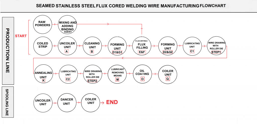
You can see the layout and flowchart of production line in FIG I9 & J9. this method is identical to the previous method in many cases , So just the important parts of this manufacturing method are described below:
FIG I9
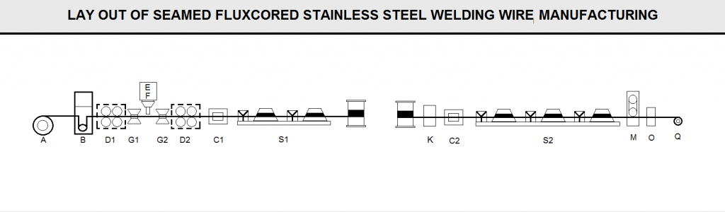
FIG L9
1) Cleaning Strip
In this process, the washing solution will clean a raw material of 304L or 316L stainless steel strip, or remove processing oil grease contaminants adhered to the surface. This is because the processing oil remaining on the strip surface or contaminants can cause an unstable arc welding process or the formation of pores. Strip surface roughness (Ra) in the range of 0.30 to 0.60 microns. When the surface roughness (Ra) of the strip is in the proper range, the control of the surface roughness of the finished wire product (Ra) and controlling the moisture content of the wire surface becomes easy. Strip surface roughness (Ra) can be controlled by a different rolling process. If non-uniform drawing of the strip surface roughness (Ra) of less than 0.30 microns, the pipe forming step, and will result in non-uniform filling rate of the lubricant can not be uniformly retained in the wire drawing process. On the other hand, if the steel sheet surface roughness (Ra) greater than 0.60 microns, the amount of increase in the wire drawing lubricant remaining in the process, the surface roughness of the finished wire product (Ra) increases, the decrease of the wire feeder wire and defect resistance.
2) Flux Mixture
the total moisture content of the flux mixture (adsorbed water and crystal water) representing a ratio by weight of a mixture of the flux should be equal to or less than 500ppm. Herein, the adsorbed water refers to water adsorbed to the surface of the material does not chemically bound, but when heated above 100 ° C to evaporate easily. It refers to a crystal water bound but not chemically and OH • HT embodiment (not molecular lattice structure) to seep moisture evaporates into the air when heated at more than I hour 950 ° C.
If the total moisture content of the flux mixture filled in the tube exceeds 500PPm, its impact on the manufacturing process increases, resulting in undesirably weld surface defects.
More details are given of the adsorbed water and crystal water in the following embodiments. Using a gravimetric method for measuring the moisture content reduced, i.e., 50 g of at least one hour flux mixture was heated at 950 ° C or above 950 ° C, and calculates the amount of evaporation of the moisture in the air.
The total moisture content of the flux (ppm) = [(Wa-Wb) / Wa] xl06 (Formula I) Formula I, Wa is weight of the flux mixture material (g), Wb is the flux mixture material is heated I at 950 ° C after hours measured weight (g).
Flux mixture including mineral, or at least two metal oxides. These fluxes contain water and water purification process is inevitably adsorbed moisture or voids penetrate the molecular structure of adsorbed from the air, part of the water in the (bright annealing heat treating process, it is to reduce the work hardening of the wire under a high temperature reducing atmosphere conditions and burning off the lubricant remaining on the surface) was evaporated from the seam, and another portion of water remaining in the tube. The inventors of the present invention, when the residual moisture is mainly known welding defects, without baking process attempts to control the moisture content, and ultimately improve the missing-notch resistance.
In order to make the total moisture content to minimize flux mixture, the present invention is measured using the same total moisture content of the final mixture by weight of the flux reduction method, measurement of various adsorbed water content and the content of crystal water flux, and had completely excluded by containing a large amount of water flux or large flux may further adsorption of moisture.
3) Flux Filling and Forming Processes
The control surface roughness (Ra) is made of a stainless steel tube. To this end, the forming breast roll arranged in series, and the number of steps used in shaping forming roll appropriately determined depending on hardness or strength stainless steel strip width and thickness, or of stainless steel.
Before completely formed into a tubular strip, containing the 500 ppm (or less) of water was poured into the flux tube. At this time, if the filling ratio is less than 10%, the volatile longitudinal welding wire, welding wire quality deteriorates. Meanwhile, if the filling ratio exceeds 30%, the flux may overflow tube, the wire may be broken during the drawing process. For these reasons, the present invention is filled is set in the range of 10% to 30% (percentage of the total weight of the wire).
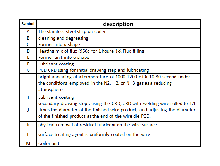
4) Drawing Step
Since the flux cored wire for stainless steel welding work hardening during the drawing step serious, so bright annealing (1000-1200 ° C) after the initial drawing step, to reduce the extent of work hardening. Then the second drawing, so that between 38% and 60% cumulative shrinkage after bright annealing process. Here, the shrinkage rate is the cumulative time of molding the wire through a plurality of molds and each mold shrinkage in.
Examples of the present invention is a drawing method for producing stainless steel welding flux cored wire used include: (i) use the primary and secondary PCD die drawing step; (H) using the first drawing step CRD, the secondary drawing PCD step using a mold; and (iii) the primary and secondary drawing step uses CRD, the final stage of the step of drawing using a mold PCD. In this manner, the actual tensile strength of the finished wire product can be 110-150 kg / mm2, a surface roughness (Ra) of 0.15 to 0.50 microns, surface micro hardness (Hv) of 370-500HV.
Whether using the CRD PCD or, if the properties of the finished wire remains within the above range, can be obtained flux cored wire for welding stainless steel having excellent resistance to wire feeding and outstanding defects. In particular, if the CRD in the second drawing process, it is recommended to use PCD drawing die at the end of the drawing process. This is because, if the CRD until the end of the drawing process, it is very difficult to control the shape of the wire, to obtain good roundness wire. Further, when the shrinkage of the secondary drawing step is below 38%, the finished product can not be sufficiently hardened wire, resulting in low surface hardness, tensile strength and low actual feedability unstable.Conversely, if the accumulated shrinkage ratio exceeds 60%, the surface roughness of the finished wire product (Ra) decreases, often resulting in the wire during wire feeding wire roll slipping. And, as the final product of welding hardening increases, the wire drawing speed is reduced, consume more mold, resulting in a corresponding decrease in productivity.
5) Bright Annealing Step
In the bright annealing step, the first reduced hardening centerline drawn, and to reduce work-hardening in the wire under high temperature reducing atmosphere, the combustion process and remove the drawing lubricant remaining on the wire surface. Preferably, bright annealing step is carried out at a temperature of 10-30 seconds at 1000-1200 ° C using N2, H2, or NH3 reducing atmosphere.
6) Physical Removal of Residual Lubricant on the Wire Surface
Purged after the drawing process in the lubricant typically physically wire remaining on the surface. For example, a blanket, or loofah discoid grindstone surface.
7) Wire Surface Coating with a Surface Treatment Agent
In order to improve the surface defects of wire feed and the finished product resistance wire, the wire coated surface treatment agent. Preferably, the surface treatment agent is an inorganic material, comprising 20-40 wt.% 1 ^ 082, at least one compound selected from the group consisting of 50-75% by weight of graphite and consisting of carbon fluoride, and selected from the group consisting of mineral oil and industrial one at least of the remaining components of the group consisting of naphthalene. In order to prevent excess wire surface is coated a surface treatment agent, after the surface treatment coating with a grinding or polishing abrasive cloth. In this manner, the wire may have a uniform surface.
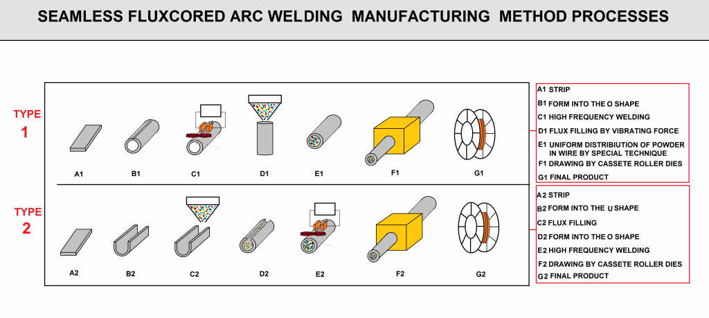
The Method for Production of Seamless Flux-cored Wire:
This method is newer and has advantages over the previous method. However, due to the high cost and difficulty of the production process, it is less popular. You can find details of this process by viewing Figures M9 and N9. There are generally two ways to produce this type of welding wire (FIG N9).
In the first method the strip will form into u and o shape and high frequency welding will run without flux-filling.in the next step the mixed flux will fill by vibrating force. Precision engineering techniques are used to uniformly fill the flux into the wire. The wire drawing process will continue after this step to reach the desired diameter.
In the second method, after forming strip into the U shape and flux filling , the seam will close by high frequency welding. The wire drawing process will continue after this step to reach the desired diameter.
FIG M9
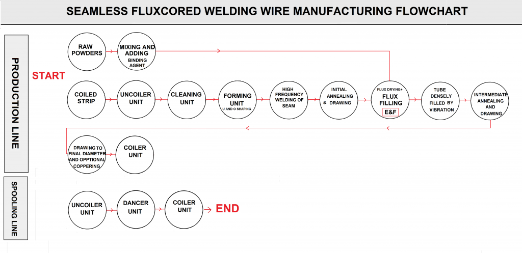
FIG N9