Introduction
Starting a flux cored wire production line is not simply a matter of buying a forming machine and a wire drawing machine. The final welding wire must have stable dimensions, a uniform flux filling ratio, reliable seam closure, a clean surface, controlled lubrication and consistent welding performance. A weakness at any stage can appear later as wire breakage, unstable feeding, excessive spatter, porosity or failure to meet the required AWS classification.
This guide explains a complete production route for gas-shielded structural-steel flux cored wire, using a nominal 2,000 metric ton per year line as a practical example. The equipment is suitable for manufacturing common AWS-classified products such as E71T-1 and E70T-1 from low-carbon steel strip. The same engineering logic is also useful for manufacturers who already operate an FCAW line but have problems with forming, filling, drawing, surface condition, productivity or final wire quality.
If you are looking for technical know-how in flux cored welding wire production, explore the [FCAW Products and Formulations Supported by WESPEC]. For a more detailed understanding of the manufacturing process, read our [Complete Guide to Flux Cored Wire Production].For detailed information about the raw materials used in a specific product such as E71T-1, read our [E71T-1 Flux Cored Wire Production Know-How].
Important: the example covers the main process equipment. A complete factory project must also consider material handling, lifting and transportation equipment, chemical analysis instruments, welding and mechanical testing equipment, maintenance facilities, utilities, laboratory requirements, packaging, building layout, safety systems and environmental controls.
How a Flux Cored Wire Production Line Works in Two Separate Section
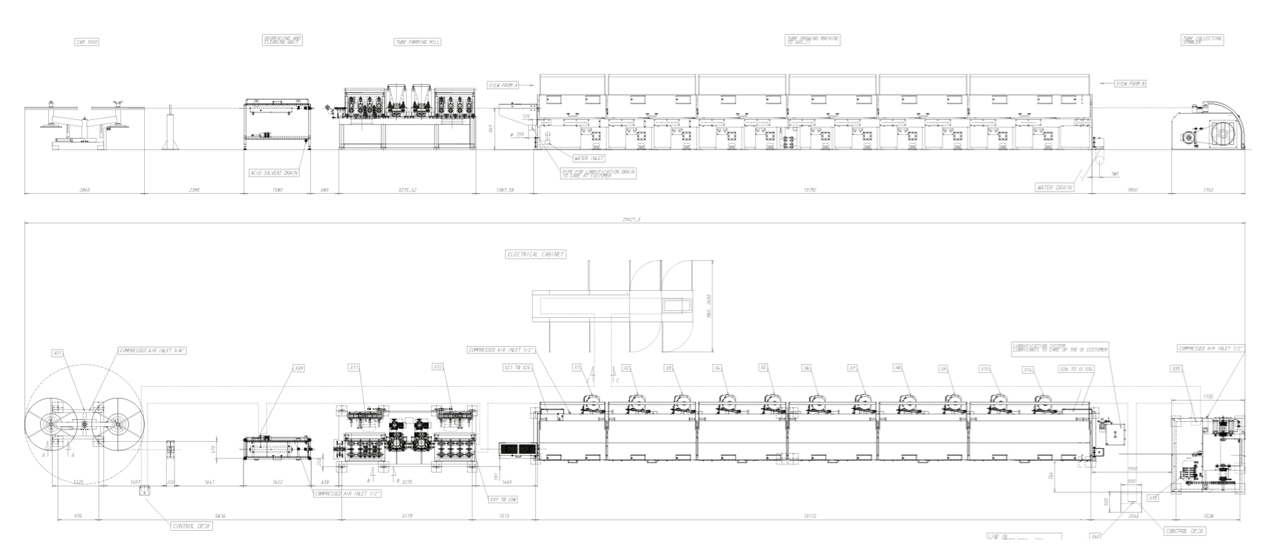
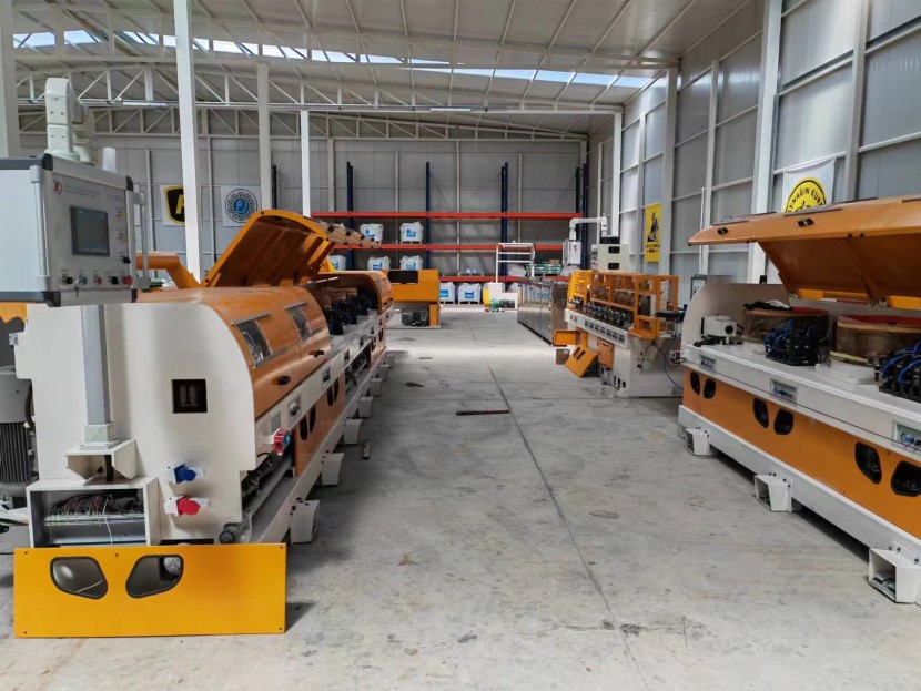
The production system is divided into two principal lines:
- Integrated forming and rough drawing line: steel strip pay-off, strip tensioning and burr scraping, cleaning and drying, ten-stage forming, servo-controlled flux feeding, six-block rough drawing, tension control and spool take-up.
- Fine wire drawing line: motorized spool pay-off, ten drawing blocks, tension control, finished-wire cleaning, oiling and final take-up.
The strip is first cleaned, gradually formed into a U-shape, filled with a measured quantity of flux, closed into a tubular wire and reduced through rolling cassettes and drawing dies. For small final diameters, die boxes are preferred in the last drawing stages because they generally provide better roundness. After drawing, the wire is cleaned, lubricated and rewound onto sale or process spools.
Example Wire Reduction Schedule: 0.8 x 12 mm Strip to 0.8 mm FCAW Wire
The following schedule shows one proposed route for converting 0.8 x 12 mm low-carbon steel strip into approximately 0.8 mm flux cored wire. The first three forming stations shape the strip without a specified circular wire diameter. Later forming stations close the tube and begin controlled reduction. Rough drawing uses rolling cassettes, while the fine drawing route changes to die boxes to improve the roundness of wire below 1.60 mm.
| Stage | Wire diameter | Reduction ratio |
|---|---|---|
| Forming 1 | Not specified | Not specified |
| Forming 2 | Not specified | Not specified |
| Forming 3 | Not specified | Not specified |
| Forming 4 | 4.60 mm | 8% |
| Forming 5 | 4.41 mm | 8% |
| Forming 6 | 4.23 mm | 6% |
| Forming 7 | 4.10 mm | 6% |
| Forming 8 | 3.98 mm | 6% |
| Forming 9 | 3.86 mm | 6% |
| Forming 10 | 3.74 mm | 22% |
| Rough drawing 1 | 3.30 mm – cassette | 20% |
| Rough drawing 2 | 2.95 mm – cassette | 20% |
| Rough drawing 3 | 2.64 mm – cassette | 20% |
| Rough drawing 4 | 2.36 mm – cassette | 18% |
| Rough drawing 5 | 2.14 mm – cassette | 18% |
| Rough drawing 6 | 1.94 mm – cassette | 20% |
| Fine drawing 1 | 1.73 mm – cassette | 18% |
| Fine drawing 2 | 1.57 mm – die box | 18% |
| Fine drawing 3 | 1.42 mm – die box | 18% |
| Fine drawing 4 | 1.29 mm – die box | 16% |
| Fine drawing 5 | 1.18 mm – die box | 16% |
| Fine drawing 6 | 1.08 mm – die box | 16% |
| Fine drawing 7 | 0.99 mm – die box | 15% |
| Fine drawing 8 | 0.91 mm – die box | 15% |
| Fine drawing 9 | 0.84 mm – die box | 12% |
| Fine drawing 10 | 0.79 mm – die box | Final pass |
This schedule must be validated against the actual strip grade, flux formulation, filling ratio, seam design, lubricant, die geometry, machine rigidity and target wire diameter. A reduction schedule that works for one product cannot automatically be copied to every FCAW formulation.
Main Equipment in the FCAW Production Line
| Section | Equipment and quantity |
|---|---|
| Integrated forming and rough drawing line | 1 complete set |
| Motorized steel strip pay-off for 800 mm spool, with pneumatic loading | 1 set |
| Strip tension unit | 1 set |
| Ultrasonic strip cleaning system | 1 set |
| Ten-head forming machine | 1 set |
| Servo-driven flux feeding device | 1 set |
| 6/560 six-block drawing machine, six rolling cassettes plus six standby die boxes | 1 set |
| Post-drawing tension unit | 1 set |
| 800 mm spool take-up | 1 set |
| Electrical control system and operation console | 1 set each |
| Fine wire drawing line | 1 complete set |
| Motorized 800 mm spool pay-off and tension unit | 1 set each |
| 10/450 ten-block drawing machine, one rolling cassette plus nine die boxes and one standby die box | 1 set |
| Finished-wire surface cleaner and oiling machine | 1 set each |
| Finished-wire take-up, electrical control and operation console | 1 set each |
| Wire pointer for 0.8-8 mm wire | 2 sets |
| Auxiliary equipment: strip slitter, 1,000 L powder mixer, layer rewinder, strip butt welder, wire butt welder and flux oven | 1 set eac |
1. Motorized Steel Strip Pay-Off
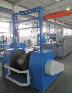
The example line uses low-carbon steel strip measuring 0.8 x 12.0 mm, with a specified thickness tolerance of +/-0.03 mm. The motorized pay-off is designed for a normal strip speed of 85 m/min and uses a 7.5 kW AC motor. Pneumatic braking controls the unwinding motion, while pneumatic lifting simplifies loading of the 800 mm outside-diameter bobbin. The customer must confirm the final spool drawing and interface dimensions.
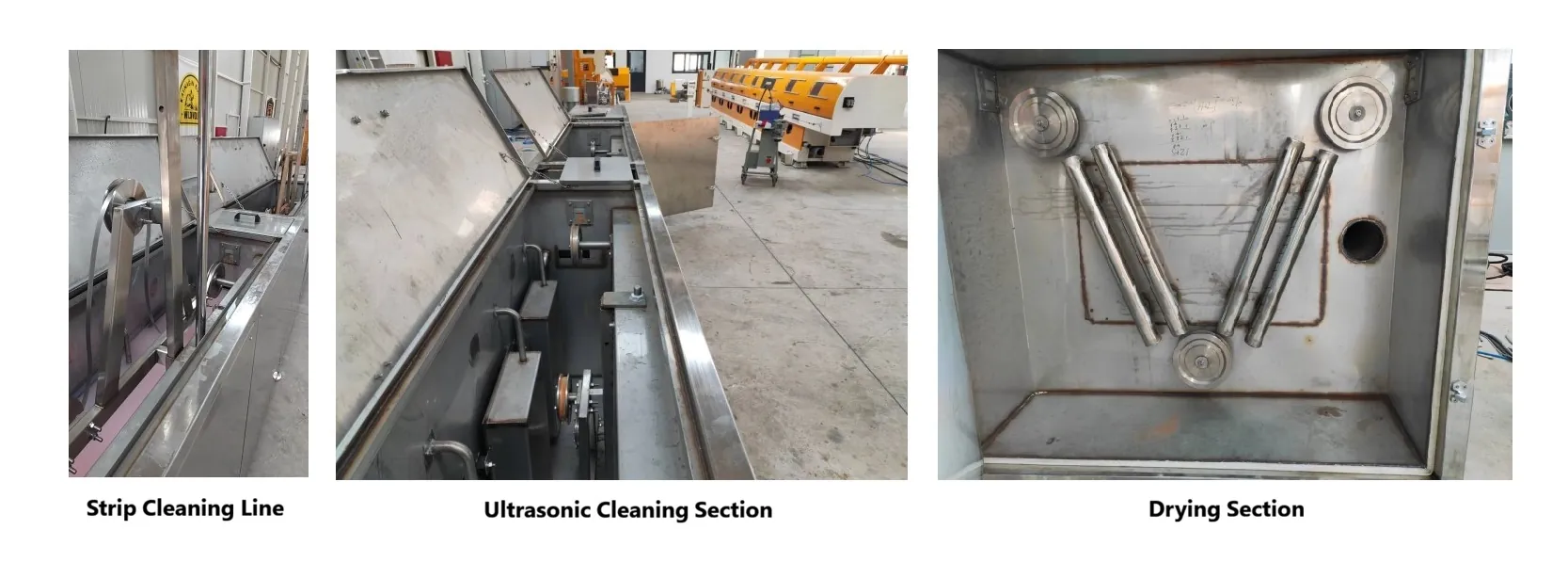
2. Steel Strip Cleaning and Drying
Surface preparation is critical. Oil, dirt, oxide and slitting residue can affect forming, seam closure, powder flow and welding-wire cleanliness. The compact strip-cleaning system combines ultrasonic cleaning, chemical cleaning, hot-water rinsing and hot-air drying. The quoted total power is 35 kW and the heating temperature is limited to 90°C or below.
3. Ten-Head Forming Machine
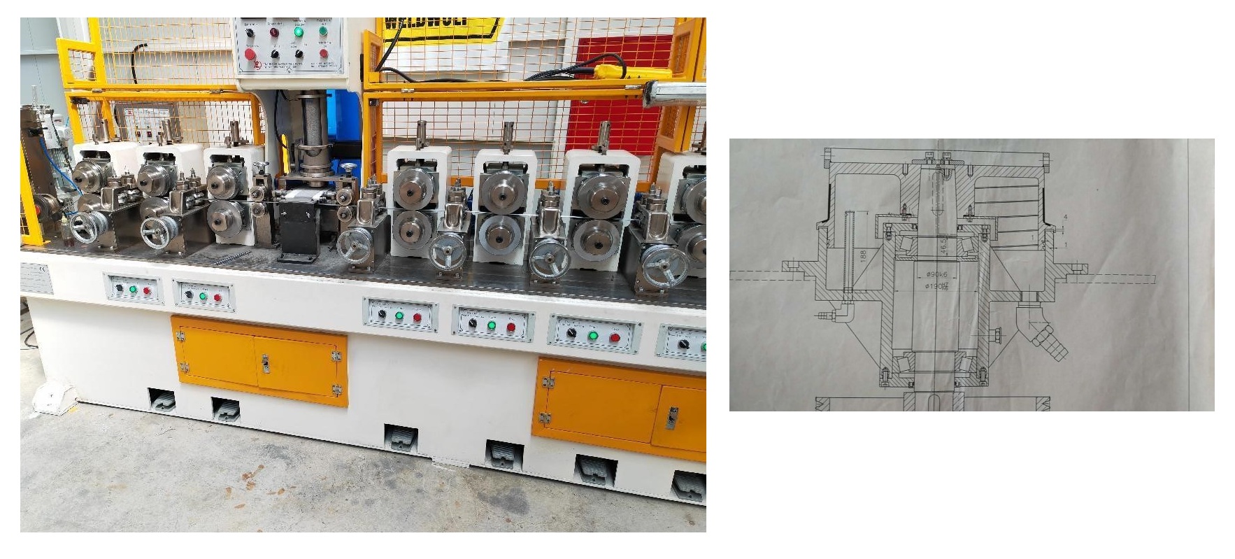
The forming section contains ten pairs of horizontal rollers and nine pairs of vertical rollers for the 0.8 x 12 mm strip. Three groups of vertical rollers are positioned before the powder feeder. The first roller group is passive; the remaining nine groups use 3 kW AC motors, giving 27 kW of roller-drive power. A 1.5 kW pulling device is also fitted.
The line can be configured with a butt-joint or overlap seam, but the interface must be selected together with the flux system, forming-roll profile and reduction schedule. The flux hopper and lifting device are stainless steel. The stated roll diameter is 148 mm.
4. High-Precision Flux Feeding System
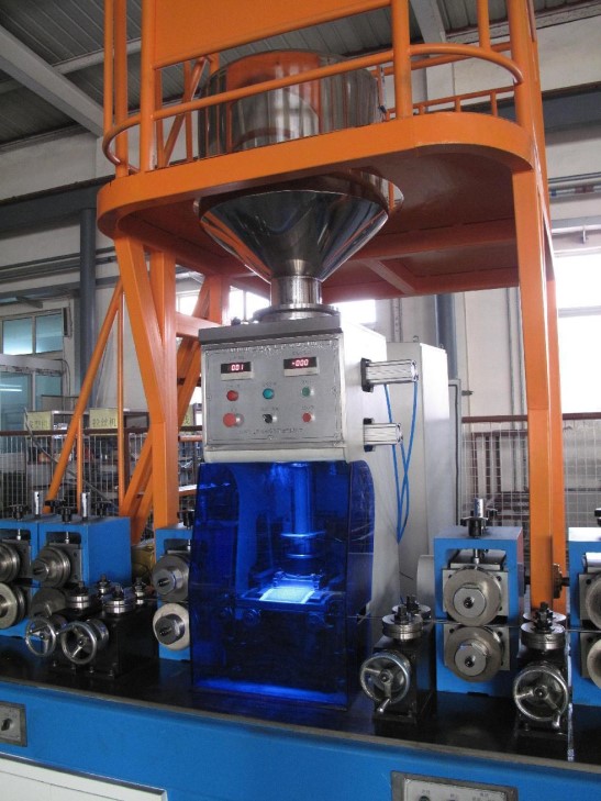
A 0.7 kW servo motor drives the flux feeding system. The operator can set the required filling ratio from the touch-screen interface. An infrared detector checks whether flux is present in the formed strip and activates an alarm when the required powder is missing.
This control is essential because flux variation affects deposited weld-metal chemistry, slag behavior, arc stability, mechanical properties and compliance with the selected AWS classification. In practice, the feeder must be calibrated by weight, and the filling ratio should be verified at defined intervals rather than relying only on a touch-screen setting.
5. Six-Block Rough Drawing Machine
Two dancer wheels between the forming machine and rough drawing machine synchronize tension and speed. Their 300 mm grooves have a ceramic-sprayed surface for wear resistance.
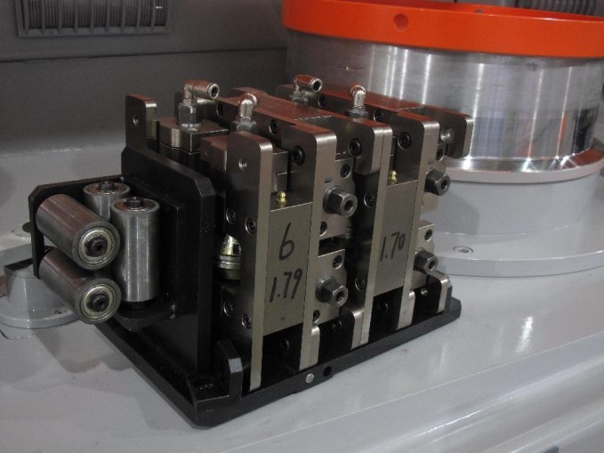
The rough drawing machine uses six 560 mm blocks and one rolling cassette at the inlet. The first block is driven by a 15 kW motor and the other blocks by 11 kW motors. The blocks are manufactured from ZG45 steel. Their working surfaces are tungsten-carbide coated to approximately HRC 60 with surface roughness Ra no greater than 0.4. Tension rollers and guide rollers also use tungsten carbide for improved wear life.
Both blocks and dies are water cooled. Internally, the block uses spiral narrow-gap water cooling; externally, it uses annular-gap air cooling. Required cooling-water pressure is 0.2-0.3 MPa, with water consumption of approximately 3.5 m³/h. Required air pressure is at least 0.7 MPa, with air consumption of approximately 0.6 m³/h. The proposed outlet wire diameter is 1.94 mm. Variable-frequency AC drives, PLC control and an HMI coordinate the line.
6. Intermediate Spool Take-Up
The 800 mm take-up is driven by a 15 kW motor and includes motor braking, pneumatic bobbin lifting and a straightener. The quoted equipment weight is approximately 1,000 kg. Dancer wheels regulate tension and speed before take-up. As with the pay-off, the customer must supply or approve the final 800 mm spool drawing.
7. Fine Wire Drawing from 1.94 mm to 0.80 mm
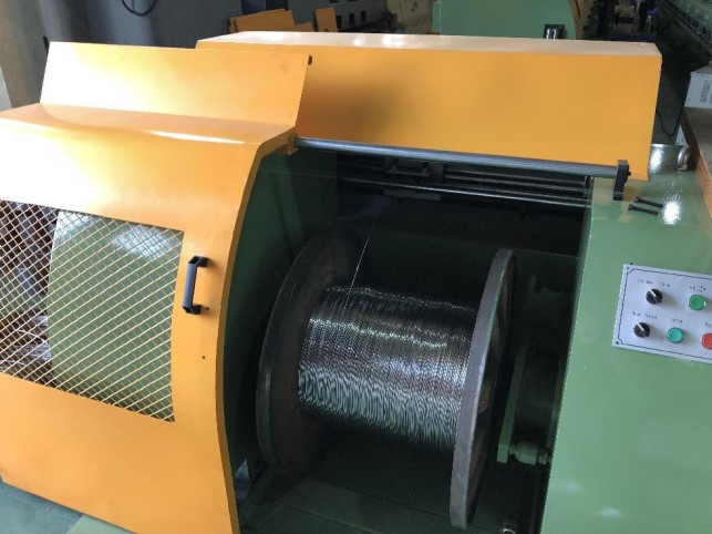
The fine drawing line receives approximately 1.94 mm wire and reduces it to 0.80 mm. It uses a motorized 800 mm pay-off, ten 450 mm drawing blocks and an 800 mm final take-up. The first block has a 15 kW motor and the remaining blocks use 11 kW motors. The ZG45 drawing blocks, tension rollers and guide rollers have tungsten-carbide working surfaces, with a target block hardness of HRC 60 and Ra no greater than 0.4.
Two dancer wheels between the pay-off and drawing machine stabilize inlet tension. Water pressure for cooling the blocks and dies is 0.2-0.3 MPa. AC variable-frequency control, PLC and HMI are used throughout, while the take-up uses a 15 kW drive.
8. Finished-Wire Surface Cleaning
Residues from drawing must be removed before oiling and rewinding. An inadequate cleaning stage can create irregular oil coverage, feeding problems, contamination of liners and contact tips, and poor appearance of the finished product.
9. Electrostatic Wire Oiling
The oiling machine uses horizontally mounted tooth-shaped electrodes. High-pressure atomization produces an oil mist of approximately 20 micrometres. A first electrostatic charge of 5-100 kV is applied to the oil mist and a second high-voltage charge, up to 100 kV, is applied to the electrodes. The resulting electric field deposits the oil uniformly on the welding wire.
Three heating systems condition the oil, compressed air and fan air. Operation can be automatic through the PLC or manual. Oil quantity can follow line speed using a detection wheel and sensor. Surplus oil is collected inside the equipment instead of being discharged.
- Power: 2,800 W
- Air supply: no more than 0.6 MPa
- Adjustable oiling range: 0.02-0.26 g/m²
- Recommended oil water content: below 0.5%
- Acid value: below 0.2 mg KOH/g
- Melting point: below 25°C
- Viscosity: 40-42 mm²/s
- Dimensions: 1,250 x 820 x 1,460 mm
- Weight: approximately 260 kg
| Wire diameter | Minimum oil coating (g/m²) | Minimum (g/10 kg) | Maximum oil coating (g/m²) | Maximum (g/10 kg) |
|---|---|---|---|---|
| 0.9 mm | 0.020 | 0.11 | 0.400 | 2.28 |
| 1.2 mm | 0.015 | 0.06 | 0.300 | 1.28 |
| 1.6 mm | 0.01125 | 0.04 | 0.225 | 0.72 |
| 2.4 mm | 0.0075 | 0.02 | 0.150 | 0.32 |
Auxiliary Machines Required for a Complete FCAW Plant
1. Steel Strip Slitting Machine
The slitting line converts master coil up to 360 mm wide into narrow strip, including the 0.8 x 12 mm strip used in this example. A different blade set is required for each strip width, such as 12 mm or 14 mm.
- Supply scope: strip pay-off, slitting unit, one blade set, strip winding machine, electrical cabinet and 800 mm take-up spool
- Maximum inlet strip width: 360 mm
- Inlet thickness: 0.1-1.2 mm; up to 1.5 mm for suitable non-ferrous strip
- Maximum number of slit strips: 15
- Width accuracy: +/-0.05 mm
- Working speed: 0.5-1.0 m/s
- Required air pressure: above 0.4 MPa
- Slitter drive: 5.5 kW
- Winder drive: 15 kW, with pneumatic braking and manual fixing
The pay-off uses an expandable mandrel: it contracts for loading and expands to secure the coil. Hard-alloy plates on both sides of the slitting unit are positioned according to strip width. The winding machine normally operates at approximately 60 m/min. After slitting, the strip can be rewound onto an 800 mm spool for the FCAW forming line.
2. Dry Flux Powder Mixer
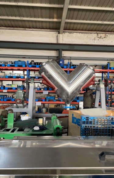
The dry-mixing vessel is stainless steel and has a nominal volume of 1,000 L. The stated practical working volume is approximately 300 L. Maximum batch capacity is around 900 kg when the powder bulk density is 3 g/cm³. A 10 kW motor drives the mixer, and a touch-screen interface is provided.
Batch size must be established from actual powder density, mixing uniformity, segregation risk and the safe working volume. Mixer loading order, mixing time and discharge procedure should be defined in the production instruction for each wire grade.
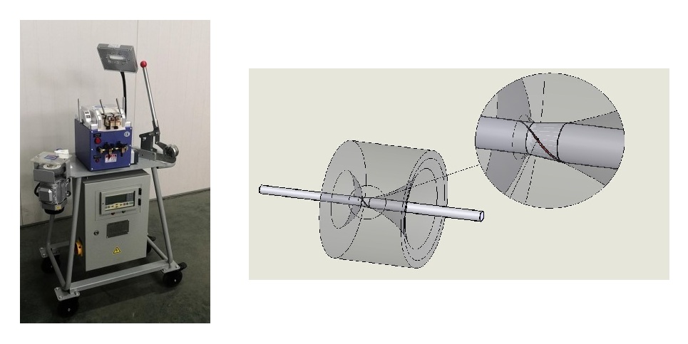
3. Steel Strip Butt Welder
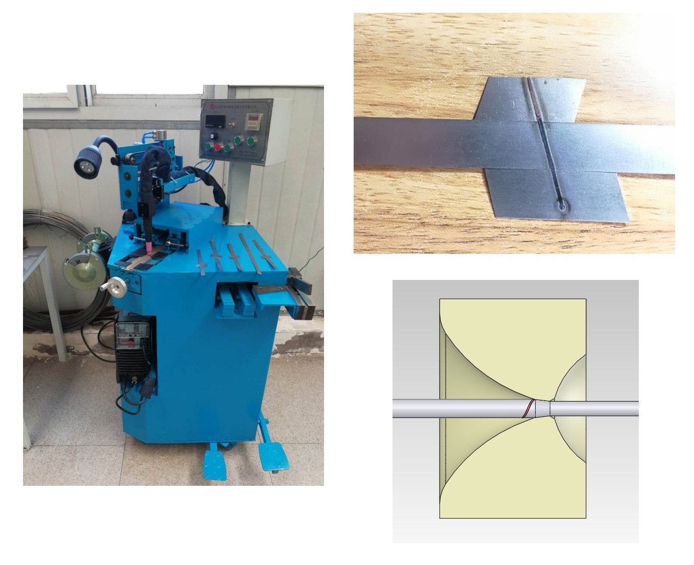
The strip butt welder joins successive strip coils so production can continue. It is suitable for carbon-steel and stainless-steel strip from 0.25 to 1.0 mm thick. The proposed unit has 1 kVA total power, 1.0-1.9 V secondary output and seven voltage-control levels. Its approximate dimensions are 500 x 350 x 1,000 mm.
The machine includes a precision clamp, grinding wheel, annealer and cutter. The supplier describes the oblique joint as having seam strength greater than the parent strip, based on tensile trials. In practice, this claim should be confirmed during FAT using the actual strip grade and thickness. The weld must survive forming and drawing without opening, while the ground joint must pass smoothly through the rolls, cassettes and dies.
4. Steel Wire Butt Welder
The microcomputer-controlled wire butt welder joins steel wire from 0.5 to 4 mm diameter. It operates on 220 V, 50/60 Hz unless customized, and has 1.5 kVA welding power. The unit includes annealing, mechanical clamping and upsetting, PLC/HMI control, a grinder and wire cutter. Its stated weight is 80 kg and its dimensions are 800 x 550 x 1,320 mm.
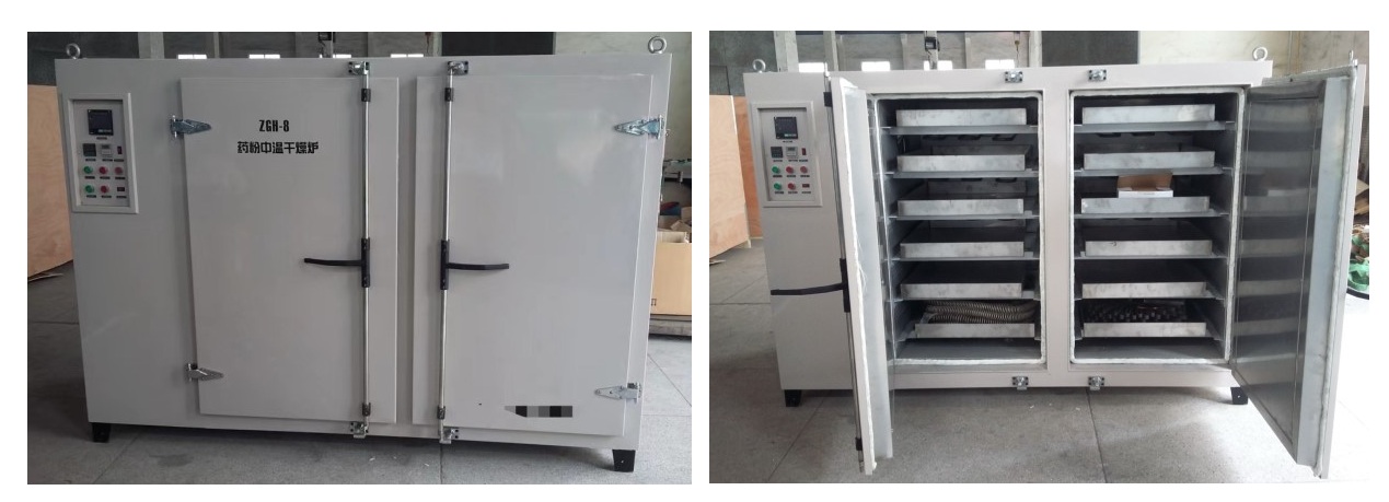
5. Flux Powder Heating Oven
Flux raw materials may require controlled heating to reduce moisture or prepare them for mixing. The proposed oven has two working chambers, each fitted with six drawers. Its internal parts and twelve 800 x 580 x 75 mm trays are SUS304 stainless steel.
| Working chamber | 1,650 mm wide x 900 mm deep x 1,265 mm high |
|---|---|
| Overall dimensions | 2,300 x 1,400 x 1,750 mm |
| Electrical supply | 380 V, 50 Hz, three phase |
| Heating power | 24 kW |
| Fan power | 0.37 kW |
| Maximum working temperature | 300°C |
| Inner material | SUS304 stainless steel |
| Outer shell | Cold-rolled steel plate |
| Discharge | From the top |
| Doors | Open from both sides |
| Control | Digital display with PID temperature control |
| Accuracy | +/-1°C |
| Sensor | K-type thermocouple |
| Safety | Independent over-temperature shutdown, motor short-circuit and overcurrent protection, and heater short-circuit protection |
A timer is included. Heating temperature and time must be based on the actual raw material and formulation; 300°C is the oven capability, not a universal treatment temperature for every FCAW powder.
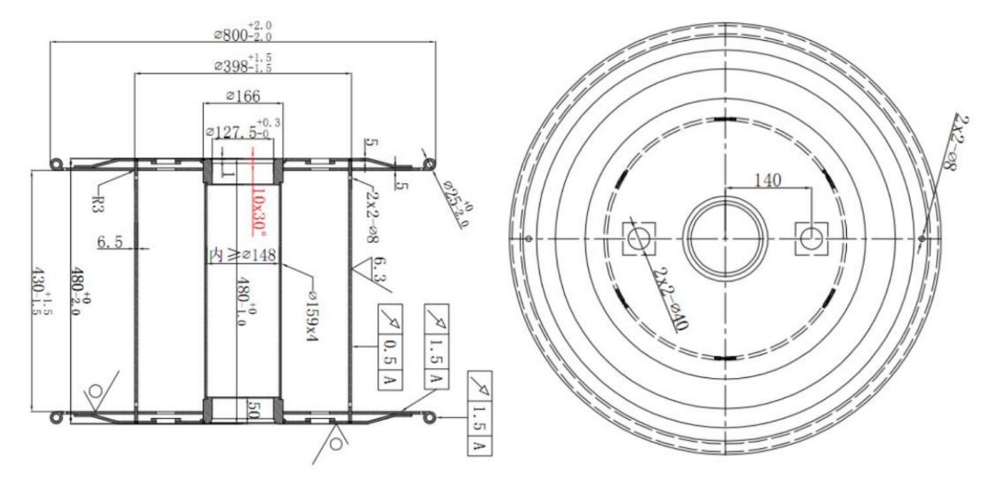
6. 800 mm Process Spools
The example supply includes ten 800 mm process spools. Final spool dimensions, hub geometry, load capacity, balance, surface finish and machine interface must be approved before manufacture. The same applies to pay-off and take-up pintles.
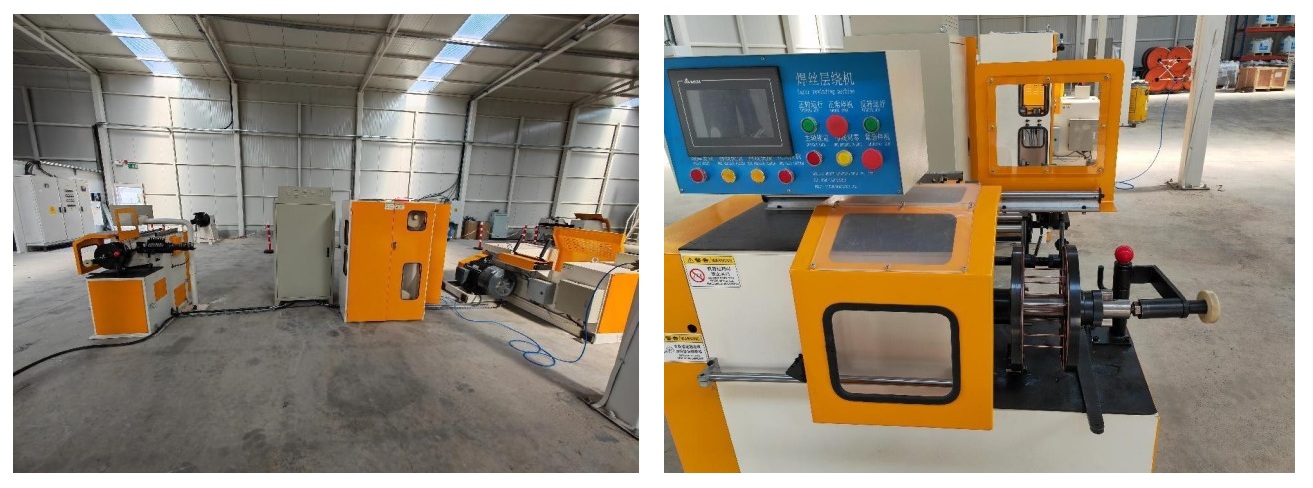
7. Layer Rewinding Machine
The rewinding line consists of an 800 mm pay-off, tension machine, take-up and electrical cabinet. It is intended to rewind the finished wire neatly onto customer spools.
- Maximum rewinding speed: 20 m/s
- Typical wire: 1.20 mm, 15 kg per spool
- Capacity: approximately 15 spools/hour or 225 kg/hour
- Pay-off spool: 800 mm, according to the approved customer drawing
- Finished spool: according to customer requirements
- Pay-off motor: 15 kW, with pneumatic pintles
- Tension control: cylinder adjusted and variable
- Take-up motor: 5.5 kW, with safety door and pneumatic braking
- Manual loading and unloading of 300 mm spools
- Twenty-six-roller straightener
The tension section includes weight-counting wheels and guide rollers. The machine stops automatically after a wire break or when the preset spool weight is reached. Speed, actual weight and set weight are displayed. PLC control provides accurate layer winding. The proposed component package includes Innovance inverter, Siemens PLC, AirTAC pneumatic parts, Autonics sensors and Schneider or equivalent first-class low-voltage components.
Common Problems in Flux Cored Wire Production
Unstable Flux Filling Ratio
Possible causes include poor powder flow, segregation after mixing, incorrect hopper geometry, feeder calibration error, changing powder density, vibration or inconsistent line speed. The solution is to control raw-material specifications, mixing, feeder calibration and gravimetric filling-ratio checks together.
Wire Breakage During Drawing
Breakage may originate from an aggressive reduction schedule, a weak strip joint, incorrect die alignment, inadequate cooling, poor lubrication, excessive work hardening or a seam that has not closed correctly. The break location and fracture appearance should be recorded before changing machine settings.
Poor Wire Roundness or Diameter Variation
Common causes are worn cassettes or dies, incorrect roll profiles, unstable dancer tension, misalignment and excessive reduction in one pass. For wire below 1.60 mm, a properly designed die-box route can improve roundness.
Seam Opening or Flux Leakage
The forming-roll sequence, strip width and thickness, seam design, filling volume and reduction schedule must work as one system. Adjusting only the final die rarely solves a seam problem created in the forming section.
Poor Feeding at the Customer’s Welding Machine
Check cast and helix, spool winding, surface cleanliness, oil level, diameter, ovality and wire stiffness. Excess oil can contaminate the feeding system, while insufficient or uneven lubrication can increase friction and contact-tip wear.
Failure to Meet AWS Performance Requirements
A mechanically stable wire may still fail welding tests. Flux formulation, raw-material chemistry and particle size, filling ratio, moisture control, strip composition and production consistency determine whether the product can achieve the required chemical, mechanical and usability performance.
What Should Be Confirmed Before Buying an FCAW Line?
- Target AWS classifications, shielding gases and wire diameters
- Required annual saleable capacity and working-shift pattern
- Steel strip grade, thickness, width, tolerances and coil dimensions
- Seam design and complete forming-roll drawings
- Flux filling-ratio range and feeder calibration method
- Reduction schedule for every target diameter
- Cooling-water quality, pressure, flow and temperature
- Compressed-air pressure, dryness and consumption
- Electrical load, control architecture, safety interlocks and software backup
- Factory layout, foundations, access, lifting and material flow
- Laboratory and welding-test equipment required for product approval
- FAT and SAT procedures using actual production materials
- Commissioning, operator training, spare parts and after-sales support
How WESPEC Supports New and Existing FCAW Manufacturers
WESPEC is an independent welding-consumables engineering and consulting team. We do not limit a project to machine selection. We can support investors and manufacturers from feasibility and equipment evaluation through raw-material specifications, formulation know-how, production instructions, factory acceptance testing, installation, commissioning, operator training, quality-control planning and final product qualification.
For an existing line, our work begins with the product and the defect. We review the strip, powder, filling ratio, forming geometry, seam, reduction schedule, cooling, cleaning, oiling, rewinding and welding-test results to identify where the problem is being created. This prevents repeated trial-and-error changes that treat the symptom instead of the cause.
Planning a new flux cored wire factory or experiencing a problem with your current FCAW line? Contact WESPEC to discuss your target products, available equipment, production capacity and present quality challenges.
0 comments
Write a comment