Flux Cored Welding Wire Approval
(Required Tests and How to Prepare Test Samples and Acceptance Citeria interpretation Based on the AWS A5.20/A5.20M:2021 Standard)
On this page, we detail the Flux Cored Welding Wire Approval according to AWS A5.20/A5.20M for the classification testing of E71T-1C (1.2 mm diameter). Compliance with these rigorous tests ensures that electrodes meet strict standards for Operator properties, chemical composition, mechanical properties, and usability requirements, which are essential for reliable performance in industrial applications.
This comprehensive Flux Cored Welding Wire Approval guarantees that the E71T-1C flux-cored welding electrodes deliver dependable performance, making them suitable for structural and heavy fabrication applications.
Also, if you want to learn more about Flux Cored welding wire production, Read This Article.
Applicable Tests
Test Plate Preparation for Radiographic and Tension and Impact Tests
Preparing Samples and Performing (Radiographic-Tension-Impact) Tests and Acceptance Criteria
Preparing Sample and Performing Chemical Analysis Test and Acceptance Criteria
Preparing Sample and Performing Fillet Weld Test and Acceptance Criteria
1-Applicable Tests for Flux Cored Welding Wire Approval
According to Table 4 of the AWS A5.20 standard, the following tests are required for Flux Cored Welding Wire Approval (E71-T1C , 1.2 mm):
- Chemical Analysis (Clause 10)
- Radiographic Test (Clause 11)
- Tension Test (Clause 12)
- Impact Test (Clause 14)
- Fillet Weld Test (Clause 15)
2-Test Plate Preparation for Radiographic and Tension and Impact Tests
The test plate specimen is fabricated as described below, and after welding, it undergoes radiographic test. If the specimen passes the test, it is then prepared for the extraction of tensile and impact test samples and for conducting the respective tests. For base metal preparation, Use base metals listed in Table 5 on page 15, such as ASTM A36/A36M or equivalent.
Base Metal Specification for Testing E71T-1C

2.1-Tips for Preparing the Test Plate for Flux Cored Welding Wire Approval:
1-Cut the Test Plates: The test Plate must be cut to the required dimensions. Do not use thermal methods for cutting under any circumstances, and only use methods that do not increase the temperature of the cutting edge.
2-Edge Preparation: Machine or grind bevel on the edges of the base plates to form a V-groove.
3-Maintain a root opening: The welder must use extreme care with special tools to ensure that the root opening is 12 mm across the gap.
4-Clean the Surfaces: Remove oil, rust, and debris from the base and backing plates using a wire brush or grinder if necessary you can use acetone or a similar solvent for a final touch.
5-Assemble the Plates: Place the back plate under the root opening of the base plates according to the drawing and Align the plates with the backing strip then Tack-weld at the ends of the plates to hold the alignment securely.
Test Plate Design and Assembly

2.2- Preparing the Welding Machine and Equipment :
To adjust the machine before starting welding, pay attention to the following points:
Select a Suitable Welding Machine: Use a constant voltage (CV) power source, which is standard for flux-cored arc welding (FCAW). Ensure the machine is capable of delivering 200–250 amps at 26 volts.
Connect the Shielding Gas: Use 100% CO₂ shielding gas. Set the flow rate to 35–50 cubic feet per hour (cfh) using a gas regulator. Verify there are no leaks in the gas lines.
Wire Feeder Setup: Install the 1.2 mm E71-T1C wire spool into the wire feeder. Set the appropriate tension on the wire feed mechanism to prevent slipping or excess feeding.
Torch Setup: Ensure the contact tip matches the wire diameter (1.2 mm). Set the electrode stick out to 5/8 inch (16 mm).
Polarity: Set the machine to DCEP (Direct Current Electrode Positive) for optimal arc stability.
Pre-Welding Verification: Perform a test weld on a scrap piece of steel to verify machine settings. Adjust voltage, current, and travel speed to ensure proper penetration and bead shape.
Flux-cored wire welding torch settings before testing

Welding Machine and Test Plate Setup before Starting the Test

2.3- Welding Stage(Execution Phase):
In the table below you can see the key parameters required for welding test plates According to the AWS :

Filling the gap between two pieces is as follows, which requires at least 6 to 9 layers of welding. This is the explicit instruction of the AWS. Two to three welding passes are made in each layer. (see table and figure below)
Number of Passes and Layers for E71T-1C , 1.2 mm

2.3.1.Points to Consider for Welding:
Root Pass
- Objective: Achieve full penetration into the backing plate with proper fusion between the base metals.
- Execution:
- Start at one end of the plate and stabilize the arc.
- Maintain a consistent arc length and travel speed.
- Ensure smooth weld bead deposition with proper tie-in to both sidewalls.
- Inspection: Visually inspect the root pass for any visible defects, such as undercut or lack of fusion.
Filler Passes
- Objective: Fill the V-groove uniformly without introducing defects.
- Execution:
- Alternate welding on either side of the joint to balance heat input and minimize distortion.
- Remove slag thoroughly between each pass using a chipping hammer and wire brush.
- Adjust travel speed and electrode angle to maintain bead consistency and prevent overfilling.
- Layer-by-Layer Check:
- Check for uniform bead width and height.
- Ensure proper fusion between successive layers.
Cap Pass
- Objective: Complete the weld with a slight convex profile that adheres to reinforcement limits.
- Execution:
- Maintain a consistent electrode motion, using a slight weave if necessary to achieve full sidewall coverage.
- Avoid excessive heat input to prevent undercut or sagging.
- Limit weld bead reinforcement to ≤3 mm.
- Final Inspection:
- Inspect the cap pass for uniformity and smooth transitions to the plate surface.
- Ensure no visible defects, such as spatter, porosity, or undercut.
2.3.2- Monitoring During Welding:
Continuously observe the arc to ensure it is stable and does not fluctuate. Monitoring the heat input is essential to maintain weld quality. Use the appropriate formula to calculate heat input and adjust parameters such as voltage, current, or travel speed as needed to stay within the target range.
Gas Coverage:
Regularly check the shielding gas flow to avoid porosity. Ensuring proper gas coverage protects the weld pool from atmospheric contamination and results in a sound weld.
Slag Removal:
After each pass, remove the slag completely using a chipping hammer and wire brush. It is crucial that the weld surface is clean and free from inclusions before beginning the next pass to maintain weld quality and ensure good fusion between layers.
Post-Welding Cooling:
Allow the weld to cool naturally in still air. Avoid forced cooling methods, such as water quenching, as they can lead to cracking. Monitor the final interpass temperature to ensure it does not exceed 325°F (165°C), maintaining proper metallurgical properties and preventing thermal stress.
Post-Welding Visual Inspection:
Inspect the completed weld for several key quality indicators:
-
A uniform bead appearance and reinforcement not exceeding 3 mm.
-
Absence of visible cracks, porosity, or other surface defects.
-
Smooth transitions to the base metal without requiring excessive grinding.
Notes About Preheat and Interpass Temperature:
Maintaining proper preheat and interpass temperatures is essential for achieving high-quality welds with E71-T1C electrodes. The preheat temperature must be at least 60°F (15°C), while the interpass temperature should not exceed 300°F ± 25°F (150°C ± 15°C). These ranges help prevent hydrogen-induced cracking and promote optimal metallurgical properties in both the weld metal and the heat-affected zone (HAZ).
Before welding begins, uniformly preheat the base plate. This slows the cooling rate of the weld, allowing hydrogen to escape and reducing residual stress. Preheating can be done using a propane or oxy-fuel torch applied evenly, or with electric resistance heaters or heating blankets for more consistent results. Always verify the preheat temperature using temperature-indicating crayons or an infrared thermometer. Measure at three points: directly at the weld joint and 75 mm (3 inches) on either side.
Controlling the interpass temperature is equally important. After each pass, measure the weld joint temperature using a thermocouple or digital thermometer. If it exceeds 325°F (165°C), allow the weld to cool naturally in still air. Avoid rapid cooling methods like water or forced air, which may cause cracking. To manage excessive heat buildup, adjust welding parameters—reduce voltage or current and increase travel speed.
Document both preheat and interpass temperatures for each weld pass in a welding log as part of your quality assurance process. Use calibrated tools for verification, both before welding starts and after each pass. Following these practices ensures weld integrity, minimizes defects, and maintains compliance with relevant specifications.
Welding of Test Plate , Zero Stage

Welding of Test Plate , Zero Stage

Welding of Test Plate , First Line

Welding of Test Plate , Welded up to the middle passes

Welding of Test Plate , Fully welded test plate

2.3.3- Heat Input Calculation and Control:
Heat input is a critical parameter in welding, as it directly affects the mechanical properties of the weld metal and the heat-affected zone (HAZ). For E71-T1C (1.2 mm diameter) electrodes, the acceptable heat input range is 25–50 kJ/in (1.0–2.0 kJ/mm). Proper control of heat input ensures optimal fusion, mechanical properties, and avoidance of defects like excessive grain growth or distortion.
Calculation of Heat Input:
Heat input (kilo joule per millimeter) is calculated using the following formula:
Where:
- Volts (V): The arc voltage set on the welding machine.
- amps (A): The welding current flowing through the wire and set for the welding machine.
- Arc Time(minutes): Welding start and end time
- Weld length(mm):Welded line length
Controlling Heat Input:
- Adjusting Welding Parameters:
- Voltage: Increasing the voltage widens the arc and increases heat input, while decreasing it narrows the arc and reduces heat input.
- Current: Increasing the current raises the deposition rate and heat input, while lowering it reduces heat input.
- Travel Speed: Slowing the travel speed increases heat input by allowing more heat to concentrate in a specific area, while speeding up the travel rate reduces heat input.
- Monitoring During Welding:
- Use a welding data logger or periodically check the parameters manually.
- Record voltage, current, and travel speed during the weld to verify heat input remains within the acceptable range.
- Controlling Consistency:
- Ensure a uniform travel speed and steady arc length to maintain consistent heat input.
- Avoid sudden stops or changes in torch movement that can create localized overheating or underheating.
- Heat Input Adjustments for Multi-Pass Welding:
- Monitor heat input between passes, especially for filler and cap passes, as cumulative heat can exceed the acceptable range.
- Allow the joint to cool if the interpass temperature approaches the maximum limit of 300°F ± 25°F (150°C ± 15°C).
3-Preparing Samples and Performing Radiographic, Tension, and Impact Tests
As shown in the figure below, the test plate sample is first assembled, and then welding is performed according to the instructions mentioned. After that, the backing and welding surface are machined and the two sides of the test plate are cut. The sample is subjected to radiography at this stage. If the quality is approved according to the standard instructions, the sample is sent to the turning unit to make 1 tensile sample and 5 impact samples according to the figure.
Tensile and impact samples are sent to the laboratory to be tested using the relevant machines. Finally, the results obtained will be compared with standard limits.
Radiographic , Tensile and Impact Test of Flux Cored Welding Wire

3.1. Radiographic Testing (Clause 11):
This test assesses the internal integrity of the weld metal, detecting possible discontinuities such as cracks, slag inclusions, or porosity.
Procedure:
-
Preparation:
-
Remove any backing material from the test assembly.
-
Machine or grind both sides of the weld so they are smooth and flush with the base metal.
-
Ensure weld reinforcement is uniform and does not exceed 3/32 inch (2.5 mm).
-
-
Radiographic Setup:
-
Position the welded test piece according to Figure 2 of the standard.
-
Select one of the following radiographic methods:
-
Film Radiography in accordance with ASTM E1032.
-
Computed Radiography (CR) in accordance with ASTM E2033.
-
Digital Radiography (DR) in accordance with ASTM E2698.
-
-
Apply inspection quality level 2-2T as specified in the standard.
-
-
Inspection:
-
Analyze the radiographic image for:
-
Absence of cracks, incomplete fusion, or incomplete penetration.
-
Slag inclusions not exceeding 1/4 inch (6 mm) or one-third of the weld thickness—whichever is greater.
-
No clustered slag inclusions whose total length exceeds 12 times the weld thickness.
-
Rounded indications must conform to the size limits shown in Figure 6.
-
-
-
Acceptance Criteria:
-
The radiographic images must not reveal any defects that exceed the limits defined in the standard.
-
3.2. Tensile Test (Clause 12)
This test evaluates the mechanical properties of the weld metal, including tensile strength, yield strength, and elongation.
Procedure:
-
Specimen Preparation:
-
Machine an all-weld-metal tensile test specimen in accordance with AWS B4.0.
-
Dimensions:
-
Nominal diameter: 13 mm
-
Gauge length-to-diameter ratio: 4:1
-
-
-
Testing Method:
-
Conduct the test using a calibrated universal testing machine.
-
Apply tensile force gradually until the specimen fractures.
-
Record the following parameters:
-
Maximum load (tensile strength)
-
Yield point (yield strength)
-
Total elongation at fracture
-
-
-
Acceptance Criteria:
-
Tensile Strength: 70–95 ksi (490–670 MPa)
-
Yield Strength: ≥58 ksi (390 MPa)
-
Elongation: ≥22%
-
Tensile Test Specimen Specification

3.3. Impact Test (Clause 14)
This test evaluates the toughness of the weld metal, particularly under low-temperature conditions.
Procedure:
-
Specimen Preparation:
-
Machine five full-size Charpy V-notch specimens from the test weld assembly in accordance with Figure 2 of the standard.
-
Ensure the following:
-
Cross-sectional dimensions: 10 mm × 10 mm
-
Parallel alignment between the notched and struck surfaces within 0.002 inch (0.05 mm)
-
Notch geometry is smooth and square, verified by etching
-
-
-
Testing Conditions:
-
Conduct the impact test at the specified temperature for the electrode classification:
-
For E71-T1C, perform testing at 0°F (−20°C)
-
-
Use a calibrated Charpy impact testing machine to determine the absorbed energy for each specimen.
-
-
Evaluation Criteria:
-
Discard the highest and lowest absorbed energy values.
-
Of the remaining three specimens:
-
At least two must exhibit absorbed energy ≥20 ft·lbf (27 J)
-
The third may be lower but not less than 15 ft·lbf (20 J)
-
The average of the three must be ≥20 ft·lbf (27 J)
-
-
Impact Test Specimen Specification

4-Preparing Sample and Performing Chemical Analysis Test and Acceptance Criteria for Flux Cored Welding Wire Approval:
Chemical Analysis Test for Flux Coed Welding Wire Approval
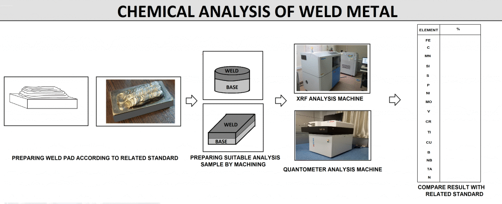
Performing a chemical analysis test for E71-T1C flux-cored wires is crucial to ensure the weld metal meets the chemical composition requirements outlined in the AWS A5.20/A5.20M standard. The procedure involves sampling, preparing, analyzing, and verifying the composition of the deposited weld metal against the standard’s specifications.
4.1. Sample Preparation
-
Weld Pad Preparation:
-
Use a clean, flat low-carbon steel base plate for the weld pad.
-
Deposit multiple passes with E71-T1C wire to build up a thick layer (typically 10–15 mm).
-
Ensure all welding parameters comply with standard requirements:
-
Polarity: DCEP (Direct Current Electrode Positive)
-
Shielding Gas: 100% CO₂ at a flow rate of 35–50 cfh
-
Maintain proper preheat and interpass temperatures to prevent overheating
-
-
Cleaning:
-
After welding, clean the weld pad with a wire brush or grinder to remove slag and oxides.
-
Ensure the surface is smooth, clean, and free of visible defects, contaminants, or foreign materials.
-
Sample Extraction:
-
Cut or machine the weld pad to extract a representative sample.
-
Methods include milling, drilling, or machining a uniform cross-section of the deposited weld metal.
-
Prevent contamination during extraction to maintain result accuracy.
4.2. Testing Methods for Chemical Analysis
Once the sample is prepared, chemical analysis can be performed using one of the following methods:
-
Spectrometric Analysis:
-
Use spark optical emission spectrometry (OES) or X-ray fluorescence (XRF) for fast and accurate elemental analysis.
-
Advantages:
-
High precision for carbon, manganese, silicon, sulfur, and phosphorus
-
Capable of multi-element analysis in one test
-
-
Procedure:
-
Calibrate the spectrometer using certified reference materials (CRMs)
-
Place the sample into the spectrometer and begin analysis
-
Record the results for each element
-
-
Wet Chemical Analysis:
-
Use standard ASTM chemical test methods if spectrometric tools are not available.
-
Advantages:
-
High accuracy for specific elements
-
-
Procedure:
-
Dissolve the sample in a suitable acid solution
-
Use titration or colorimetric techniques to analyze specific elements
-
Apply gravimetric methods for elements such as manganese or sulfur
-
4.3. Key Elements and Their Specifications
The following elements must be analyzed in E71-T1C deposited weld metal:
| Element | Typical Range for E71-T1C | Impact |
|---|---|---|
| Carbon (C) | ≤ 0.12% | Controls hardness and toughness |
| Manganese (Mn) | 1.40–1.85% | Improves strength and toughness |
| Silicon (Si) | 0.25–0.65% | Enhances deoxidation and weld cleanliness |
| Sulfur (S) | ≤ 0.03% | Excess can cause weld brittleness |
| Phosphorus (P) | ≤ 0.03% | Excess can lead to cracking |
Ensure all results fall within the specified limits in AWS A5.20/A5.20M.
4.4. Evaluation of Results
-
Data Interpretation:
-
Compare measured values with the standard composition limits.
-
Confirm that no element exceeds the allowable range.
-
Verification:
-
Check calibration records of spectrometers or chemical reagents.
-
Repeat the analysis if results significantly deviate from expectations.
-
Acceptance Criteria:
-
All elements must fall within the required range for E71-T1C weld metal.
-
Any non-conforming result requires corrective action, such as checking raw materials or adjusting welding parameters.
5-Preparing Sample and Performing Fillet Weld Test and Acceptance Criteria for Flux Cored Welding Wire Approval:
For E71T-1C classification, two fillet weld test assemblies are required: one welded in the vertical position and the other in the overhead position. Both tests evaluate the electrode’s usability, fusion characteristics, and the quality of the resulting welds. After welding, inspections through visual examination, macroetch tests, and dimensional verification ensure compliance with the standard’s acceptance criteria.
5.1. Test Assembly Preparation (Applicable to Both Positions)
-
Base Metal:
-
Use the specified base metal from Table 5 (e.g., ASTM A36 or equivalent).
-
Each piece must have:
-
Thickness: 3/8 inch (10 mm) to 1/2 inch (12 mm)
-
Width: 3 inches (75 mm)
-
Length: 12 inches (300 mm)
-
-
Joint Configuration:
-
Assemble the plates in a T-joint configuration:
-
The web (vertical plate) must have a straight, smooth, and clean edge.
-
The flange (horizontal plate) must be clean and free of rust, oil, or debris.
-
-
Securing the Plates:
-
Ensure intimate contact along the entire joint length at the faying surfaces.
-
Secure the assembly with tack welds at both ends to maintain alignment during welding.
5.2. Fillet Weld Test – Vertical Position
Welding Setup:
-
Position:
-
Place the assembly vertically, with the standing plate upright and the base plate horizontal.
-
Welding progression options:
-
Upward (3G-Up): Offers better penetration control
-
Downward (3G-Down): Faster but with less penetration
-
-
Welding Parameters:
-
Electrode: E71-T1C, 1.2 mm diameter
-
Polarity: DCEP (Direct Current Electrode Positive)
-
Shielding Gas: 100% CO₂, 35–50 cfh flow rate
-
Voltage: 22–26 V
-
Current: 160–200 A
-
Travel speed: Adjust for smooth bead formation and adequate penetration
-
Welding Technique:
-
Maintain a slight upward torch angle (~5°–10°) for upward welding
-
Use a steady weaving motion to ensure good edge fusion
-
Avoid excessive arc length to minimize spatter and porosity
-
Cleaning Between Passes:
-
For single-pass welds, remove slag using a wire brush or chipping hammer
5.3. Fillet Weld Test – Overhead Position
Welding Setup:
-
Position:
-
Place the assembly in the overhead position (4F), with the flange plate above and the weld deposited against gravity
-
Welding Parameters:
-
Use the same parameters as for the vertical test:
-
Electrode: E71-T1C, 1.2 mm diameter
-
Polarity: DCEP
-
Shielding Gas: 100% CO₂, 35–50 cfh
-
Voltage: 22–26 V
-
Current: 160–200 A
-
Stickout: 5/8 inch (16 mm)
-
-
Welding Technique:
-
Maintain a slight drag angle (10°–15° toward the weld)
-
Use a consistent travel speed to prevent excessive buildup or dripping
-
Apply short weaving motions if needed to control bead shape and tie-in
-
Gravity Control:
-
To counteract gravity, slightly reduce heat input by increasing travel speed
-
Keep arc length steady to avoid spatter and undercut
Fillet Weld Test Assembly for Flux Cored Welding Wire Approval

5.4. Inspection of Welded Test Assemblies
After completing both welds, the test assemblies are assessed for quality and usability through the following inspections for Flux Cored Welding Wire Approval:
-
Visual Examination:
-
Inspect for uniform bead appearance, proper leg length, and smooth transitions.
-
Ensure there are no visible defects such as cracks, undercut, excessive spatter, or porosity.
-
Fillet Weld Size:
-
Fillet weld dimensions must meet the required parameters for both convex and concave welds.
-
In convex welds, the L and S dimensions are nearly equal.
-
In concave welds, these two values differ.
-
The measurement method for these parameters is as shown below:
How to Use a Gauge to Measure Fillet Weld Dimensions

- Macroetch Test:
- Section the welds and polish the cross-section.
- Etch the section using a 10% nitric acid solution or similar reagent.
- Evaluate for:
- Fusion: Full fusion to the base metal and between weld passes.
- Penetration: Adequate root penetration.
- Soundness: Absence of slag inclusions, cracks, or voids.
Macro-Etching Test of Fillet Weld

5.5. Acceptance Criteria
The welded test assemblies must satisfy the following requirements:
-
Fusion:
-
There must be complete fusion between the weld metal and the base plates.
-
Weld Size:
-
The fillet weld must be uniform and must not exceed 3/8 inch (10 mm).
-
The L and V parameters must conform to the values provided in the relevant table.
-
Defects:
-
No visible cracks, slag inclusions, or porosity beyond acceptable limits are permitted.
-
The weld profile must be smooth, with no undercut or excessive reinforcement.
-
Macroetch Examination:
-
The weld must show internal soundness with no signs of lack of fusion, incomplete penetration, or other discontinuities.
Fillet Weld Test Acceptance Criteria According to AWS A5.20
