Some Facts Concerning The Profile of a Drawing Die
The Performance of a Drawing Die is Largely Dependent on:
-
The Drawing Angle.
-
The Shape of the Reduction Zone.
-
The Length and Shape of the Bearing.
Drawing Angle
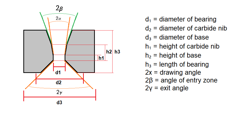
The optimum drawing angle is determined primarily on the basis of the reduction in area, wire material and lubrication.
It is a well-known fact that the optimum angle must be maintained to ensure satisfactory and uninterrupted drawing.
However, grinding may introduce deviations of several degrees.
The results obtained are dependent on the scope available to the die grinder for checking the actual angle obtained. A PS 300 will provide him with the means for fast and reliable checking.
Shape of the Reduction Zone
Straight conical dies often provide better drawing conditions than dies with “trumpet-shaped” reduction zones. The supply of lubricant is more satisfactory and the reduction geometry is more favourable. The straight reduction zone provides a somewhat smaller clearance between the wire and the drawing die and this is favourable in building up a pressure of the lubricant. In a die which is not worn, the optimum angle can be obtained along the whole of the reduction zone. This will be shorter than in the “trumpet-shaped” die and this is advantageous for lubrication. The magnified trace of the profile drawn by the PS 300 provides the simple means for checking that the shape of the reduction zone is the most favourable.
Length and Shape of the Bearing
The length of the bearing is of vital importance for the useful life of a die. This length can readily be checked by means of the PS 300.
The shape of the bearing is also very important for the production results.
Illustration (ISO-Standard vs. “trumpet shape”)
The size of the wire leaving the die is determined by the minimum diameter of the hole—designated Rₘᵢₙ in the figure—in a newly-ground die. The largest permissible size of the wire leaving the die is known as Rₘₐₓ. The figure illustrates that the minimum volume of carbide which must be worn away before the wire leaving the die will attain the Rₘₐₓ dimension is appreciably greater (the shaded surfaces) on a straight bearing than on a rounded bearing. This implies that more wire can be drawn through a straight bearing before regrinding becomes necessary.
Even if a determined effort is made to produce a die with a good shape of the bore, satisfactory results have often proved very difficult, owing to the fact that the bore cannot normally be inspected. Checks by means of the PS 300 have shown that dies have often been approved in spite of the complete absence of a straight cylindrical bearing.
Accurate inspection is also required if the bearing is to be ground with a certain amount of taper in the direction of drawing. Analysis has shown that the area of the wire in contact with the bearing can be reduced appreciably, even if the taper is as small as a few tenths of a degree. This implies that the frictional component of the total drawing force (originating from the bearing—frequently 10–20 % of the total force) can be appreciably reduced by the provision of such a taper.
The drawing force often employed is about 60–70 % of the yield load of the wire. However, recordings show that the drawing force can attain instantaneous peaks close to the yield load of the wire. If the yield load is exceeded, failure of the wire can easily take place. The risk of wire failure can be reduced by employing a correctly ground die and thus increasing the margin.
Drawing Die Cross Section

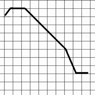
The Below Image illustrates the form of a drawing die measured after polishing. The bearing length and diameter can be checked as well as the drawing angle.
A die with a correct shape will give a longer production run before its next repolishing.
Drawing Die Cross Section Before Use

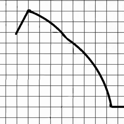
The profile shows a die measured after use. This die was incorrectly polished and had no distinct bearing. Excessive wear has occurred due to incorrect shape.
Drawing Die Cross Section After Use

