Experimental Testing of a New Approach to the Development of Welding Materials
V.L. Mazurovsky, M.I. Zinigrad and L.I. Leontiev
ABSTRACT. Research on the design and fabrication of an experimental industrial batch of flux-cored wires based on a new approach to the development of welding materials is described. The approach is based on mathematical modeling of an industrial welding process and a phenomenological model of the nonequilibrium crystallization of the molten metal in a weld pool. The results of the research performed are presented.
Introduction
The new approach to the design of welding materials proposed in [1, 2], the phenomenological model of the nonequilibrium crystallization of the molten metal in a weld pool and the accompanying carbide-formation processes in an iron-carbon weld deposit described in [3, 4], the mathematical description of a new constitution diagram of the matrix of a weld deposit described in [5], and the computer-aided design (CAD) system for welding materials described in [6-9] are all in need of thorough testing to prove that they are workable and that they faithfully describe real processes.
Organization and objectives of the experimental studies
The important technical problem of the shock-abrasion wear of the walls of a loading hopper manufactured from 1501 Gr. 161-400, 151-400 (BS United Kingdom) steel under the action of a chemically inert dry bulk material was chosen for performing the experimental studies. This problem can be solved by creating a special protective coating on the hopper walls that is capable of withstanding the action of the environment. This requires:
- Designing a special welding material based on the new approach proposed in [1, 2] using the CAD system described in [6-9] for the purpose of applying a protective coating to the walls of a loading hopper.
- Fabricating a special welding material in the form of a batch of self-shielded or gas-shielded flux-cored wires with a diameter of 2.0 mm on the basis of the design results.
- Hardfacing specimens (that imitate a real workpiece, i.e., a hopper wall) using the flux-cored wires under welding conditions determined by the design results. The required number of samples for performing full-scale testing, metallographic studies, x-ray diffraction analysis, and chemical analysis were cut from each specimen by a “cold” method.
- Performing full-scaling testing, metallographic studies, x-ray diffraction analysis, and chemical analysis on the samples; providing for systematic recording of the results of the testing, studies, and analyses; treating and analyzing the results of the studies.
- Using the results of the analysis to verify the design solution and to determine the equivalence of the characteristics of the weld deposit obtained to those determined in the design solution.
- Making appropriate corrections for any significant disparities found to the carbide-formation model and to the mathematical description of the new constitution diagram, as well as appropriate changes to the software of the CAD system and the structure of the expert system.
A technical specification for designing the new welding material was written within the approach proposed in [1]. It included the following:
- purpose and principal characteristics of the material being designed;
- expected (desired) set of functions and properties of the design object;
- area of application;
- limiting values of the parameters of the hardfacing process;
- characteristics of the hardfacing equipment employed;
- desired relative wear resistance of the weld deposit in comparison to the unprotected material (whose wear resistance is taken as unity);
- design route;
- a complete set of input technical documentation.
Design Work
The first design step specified in the new approach is an analysis of the environment and the loading of the workpiece [1]. In the second step, the workpiece is analyzed to determine its composition, a set of its properties, its geometric characteristics, its structural features, etc. A package of input data on the workpiece is generated in parallel. The third step, which is the most important, determines the nature of the interaction between the workpiece and environment on the basis of the package of input data from the first two steps and the corrective actions of the system operator. During this process, knowledge about this interaction is generated, which is recorded in a knowledge base and can be used by the system for subsequent projects, and a model of the interaction with a description of the processes that occur is constructed [10, 12, 14]. In our specific case, it was determined that the hopper walls absorb the shock-abrasion action of the free-flowing soil, which can be characterized as dry fiction in the case of particle diameters exceeding 80 microns and as microcutting in the case of smaller particle diameters. The inner clumps impart shock action that creates normal (up to 30-50 kgf/mm2) and shear (up to 25-40 kgf/mm2) stresses in the hopper walls. Individual peak shock loads can exceed the limiting strength of the hopper walls (50 kgf/mm2) and cause local cracking. Microcutting, which causes intensive wear of the hopper walls (4-5 mg/sec·m2), poses a special danger. The remaining types of mechanical effects cause wear that does not exceed 2 mg/sec·m2 [12].
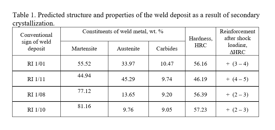
Based on the analysis of the representation of the nature of the environment–workpiece interaction and the associated processes obtained, we next perform the main design step, i.e., generation of a representation of the required structure of the weld deposit. The representation is generated on the basis of the data package obtained as a result of the work performed in the preceding steps and the knowledge stored in the knowledge base (KB) of the expert system. In the CAD system developed in [6-9], this base contains a knowledge model that is generated on the basis of the results of fundamental studies of the workability of machine parts and designs under the action of abrasion and shock wear and the results of establishing structure–wear-resistance relationships for the metal [10-14]. This step revealed that the special welding material must ensure the formation of a weld deposit that has a base structure of finely acicular or acicular martensite and metastable austenite (30-50 wt. %) with carbides uniformly distributed in it (5-15 wt. %). Under severe shock loading, the metastable austenite absorbs part of the shock energy and transforms into martensite, which strengthens the weld deposit and increases its wear resistance. An alloying system in which the region of martensitic transformation is displaced into the room temperature range (Ms < 120°C, Mf< 0°C) was calculated. It permits maintenance of a considerable amount of austenite supersaturated with alloying elements, including elements that form substitutional solid solutions with austenite (Ti, C, and N) until completion of the crystallization of the weld deposit, which renders the austenite unstable upon plastic deformation [15]. Thus, the austenite decomposes upon shock loading or microcutting into martensite and carbides, i.e., additional strengthening of the weld metal or an increase in its wear resistance occurs.
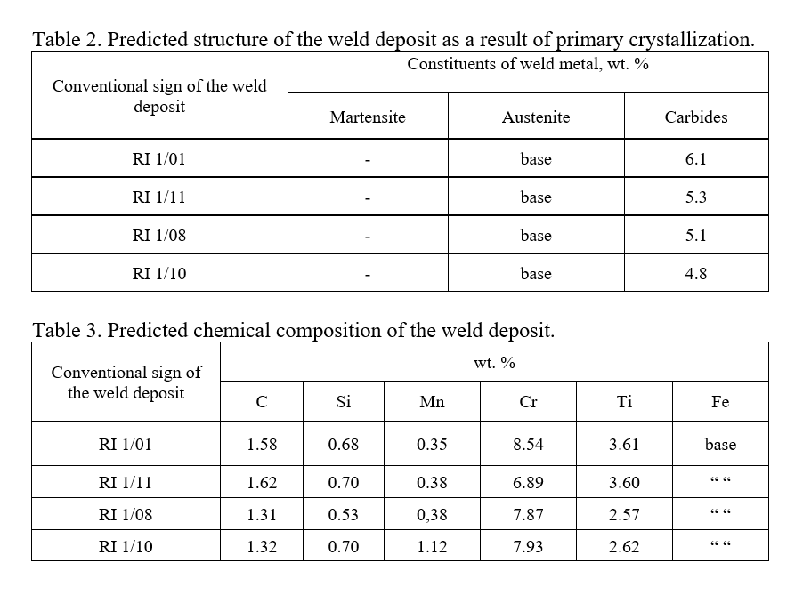
Now that a representation of the required (secondary) structure of the weld deposit has been generated, we can move on to calculating the primary structure (the structure obtained as a result of primary nonequilibrium crystallization of the weld pool) and the chemical composition of the weld metal. This calculation involves solving an inverse problem, in which the input parameters are the secondary structure of the weld metal and the values of the parameters of the thermal-straining cycle during welding. The calculation is performed in an interactive mode with a dialog between a human expert and the expert system and is based on the phenomenological model of the nonequilibrium secondary crystallization of the weld metal, the accompanying precipitation of secondary carbides [3, 4], and the mathematical description of a new constitution diagram [5]. The input data on the secondary structure of the welding materials designed are presented in Table 1. The results of the calculation of the primary structure and chemical composition of the weld deposit for four welding materials designed are presented in Tables 2 and 3, respectively.
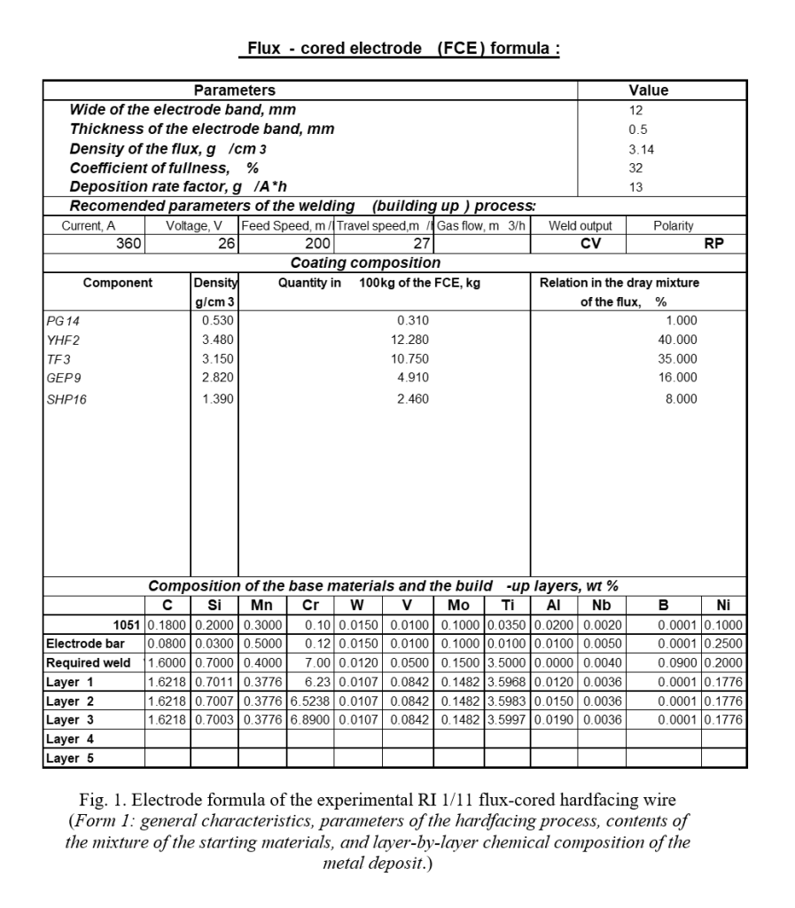
Based on the information obtained regarding the required primary structure and chemical composition of the weld deposit (Tables 2 and 3), we can determine the electrode formulas of the special welding materials designed. The electrode formula contains complete information regarding the structure, properties, and functions of the welding material designed, as well as the contents of the mixture of the starting materials, the fabrication technology (route), and the recommended welding (hardfacing) conditions. The calculation is performed in an interactive mode with a dialog between the operator and the expert system. The calculation base is a package of applications that was developed on the basis of the mathematical model of a technological welding process described in [2] and the phenomenological model of the primary nonequilibrium crystallization of a weld metal described in [3, 4].
To test the results obtain, we performed a calculation that involved solving the direct problem, i.e., determining the chemical composition, primary structure, secondary structure, and service characteristics of the weld metal. The design results, i.e., the electrode formulas of the welding materials, served as the input parameters for the calculation.
Figure 1 presents a fragment of the electrode formula of one of the consumables designed.
Technological Experiment
The next step of the experimental work was to fabricate an experimental batch of specialized welding materials in accordance with the technological requirements determined in the design steps.
Flux-cored wires were fabricated from a cold-rolled ribbon (1008 steel) with a 12 × 0.5 mm cross section on a special laboratory wire-drawing machine. The required mixture of powered materials for the core of the flux-cored wires was prepared in a laboratory mixer. The composition of the mixtures prepared for each flux-cored wire corresponded to the composition indicated in their electrode formulas (Fig. 1). All the wires had a diameter of 20 mm with closing of the steel ribbon along a straight seam. All together, 4 kg of flux-cored wires (1 kg of each) were fabricated. The hardfacing was carried out in three layers on a model workpiece (a vertical sheet of 1501 steel with a thickness of 16 mm) in accordance with the recommended hardfacing conditions in the electrode formulas of the respective welding materials (Fig. 1). Samples measuring 80 × 35 mm (the thickness included the thickness of the sheet (16 mm) and the thickness of the hardfacing deposit (5-6 mm)) were cut from the model workpiece. The cutting was performed so that the direction of the axes of the samples would coincide with the hardfacing direction for some of the samples and would be perpendicular to it for others. The first group of samples was used for x-ray diffraction analysis, chemical analysis, and hardness measurements. The second group of samples was used to perform metallographic studies and full-scale testing. Templates for studying both cross sections and the surface of the upper (third) layer of the weld deposit were cut from the samples obtained.
Metallographic studies and full-scale testing
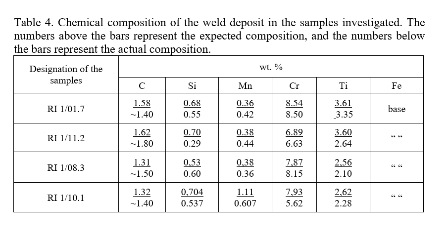
The chemical composition of the weld deposit in the samples was determined in the upper layer of the deposit. Table 4 compares the expected (calculated) and experimentally determined chemical composition of the hardfacing deposits.
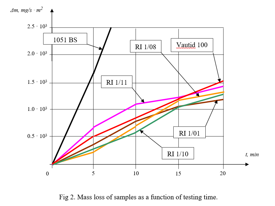
To determine the wear rate of the hardfacing deposits, they were subjected to full-scale testing on a laboratory testing unit that imitates the real picture of the wearing of hopper walls. Samples hardfaced with the expensive high-alloy wear-resistant Vautid-100 alloy (from Vautid Ltd., Germany) as well as samples of 1051 steel were tested simultaneously. Figure 2 presents plots of the dependence of the mass loss of the samples on the testing time. The plots presented reveal that the hardfacing materials developed provide a weld deposit that is resistant to the effects of shock-abrasion wear. The wear rate of the hardfacing deposits is 5-6 times smaller than the wear rate of 1051 steel and amounts to 80-90% of the wear rate of layers deposited by the expensive high-alloy (more than 32% Cr) hardfacing material Vautid-100 (Germany).
To investigate the phase changes in the alloy, the samples were subjected to shock treatment in a special laboratory device after the shock loading.
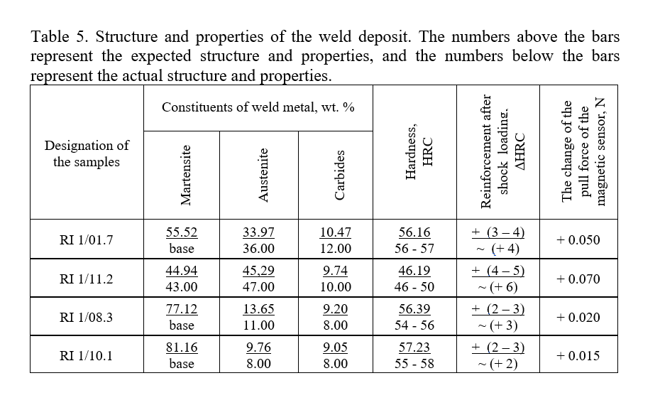
The phase changes (g ® a transformations) at the shock loading site were evaluated by varying the pull force of the magnetic needle sensor before and after shock loading. Generalized data on the change in the pull force of the magnetic sensor (an increase in the pull force of the magnetic sensor attests to a decrease in the content of the nonmagnetic g phase in the hardfacing deposit, i.e., to the occurrence of the g ® a transformation under the action of shock loading) are presented in Table 5. The data presented show that the RI 1/11 alloy, which contains the largest amount of residual austenite (approximately 47%), provides the most effective strengthening. The hardness of the weld deposit immediately after hardfacing and after shock loading was studied using a Rockwell-Wilson tester. Table 5 presents the calculated and experimental values of the hardness of the hardfacing deposits immediately after hardfacing and the increases in hardness (ΔHRC) after shock loading.
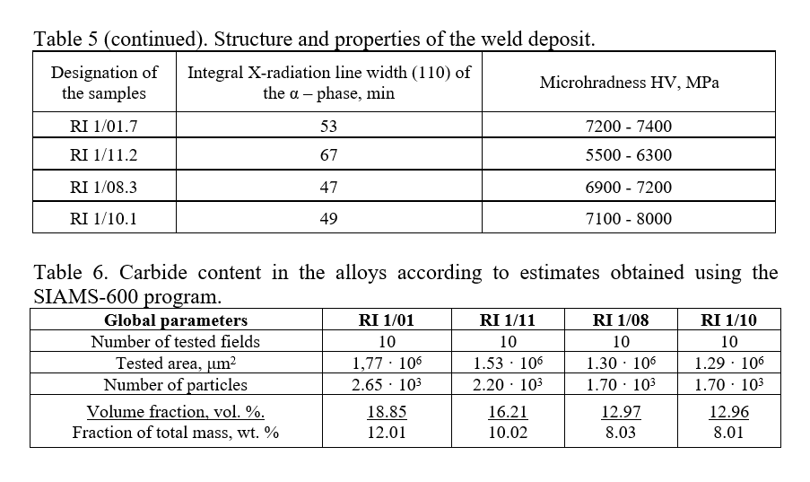
The microstructure of the weld deposit was studied by standard metallographic methods on a Zeiss Axiolab optical microscope after etching microsections in a 4% alcoholic solution of HNO3. The microhardness on the surface of the microsections was determined in parallel under a load of 100 gf by a Buehler microhardness tester. The phase composition of the weld deposit was investigated on a DRON-0.5 x-ray diffractometer in Fe Kα radiation. Profiles of the α phase (110) line and of the austenite (111) line were recorded. The ratio between the intensities of these lines was analyzed to determine the quantity of residual austenite.
After hardfacing, all the samples had a structure that is typical of a hardfaced cast metal, viz., a cellular dendritic structure. Because of the high carbon content and the presence of alloying elements (the total content of the alloying elements did not exceed 12%), which inhibit the decomposition of austenite in the 600-400°C temperature range, as well as the high cooling rate (50-70 K/sec), the g ® a transformation occurred in the metal. As a result, a martensitic matrix structure with a varying amount of residual austenite, which depended on the chemical composition, and carbide phases, which were distributed relatively uniformly in the matrix, mainly formed. Finely acicular martensite and residual austenite were observed in all the samples. Generalized data from the metallographic studies, x-ray diffraction analysis, and hardness and microhardness measurements of the samples are presented in Table 5.
The quantitative carbide content was determined using the SIAMS-600 image analysis computer program (SIAMS Ltd., Ekaterinburg) (Table 6). Summarized results of the studies are presented in Tables 4-6.
An analysis of the results of the studies and the full-scale testing performed revealed that all the materials developed can be employed for the purpose of applying a protective coating, since they have characteristics indicating their resistance to wear and shock loading that significantly exceed (by five to six fold) the analogous characteristics of 1501 Gr. 161-400, 151-400 (BS United Kingdom) steel. However, the optimal properties are displayed by the RI 1/01 alloy, which provides the lowest wear rate, the highest hardness, a high extent of occurrence of the g ® a transformation, and considerable relative strengthening after shock loading, as indicated by the large change (increase) in the pull force of the magnetic sensor (see Table 5).
Evaluation of the equivalence of the model based on the testing results. Revision of the model and the software of the CAD system for welding materials
The equivalence of the model was estimated on the basis of a comparison of the results of the design solution and the results obtained during the testing. As follows from the data presented, on the whole, the discrepancies do not exceed 20%, indicating the high equivalence of the phenomenological model developed to the real process of nonequilibrium crystallization of the molten metal in the weld pool. The discrepancies discovered in the evaluation of the amounts of austenite exceed 20%. These discrepancies are significant and point out a need to revise the model. The analysis of the discrepancies was implemented in the form of correction functions. The functions must ensure a minimal deviation of the amount of austenite from the design solution, i.e., the partial derivatives with respect to these functions must be equal to zero. By solving the system of equations obtained, we determined the correction coefficients for the functions, which ensured convergence of the calculation results with the real data. Next, appropriate changes were made to the software of the CAD system, the knowledge representation model, and the knowledge bases and databases of the expert system.
Conclusions
- To test the new approach, a task of designing and fabricating a batch of specialized flux-cored wires for obtaining hardfacing deposits that resist shock-abrasion wear has been devised. The structure of the required protective coating has been determined, and a technical specification for designing a special hardfacing material for producing it has been developed.
- Hardfacing flux-cored wires for applying a protective coating that is stable under the conditions of shock-abrasion wear to low-carbon and low-alloy steels have been designed on the basis of the technical specification using the CAD system for welding materials. An experimental batch of flux-cored wires has been fabricated on the basis of the design results, and samples have been hardfaced under the calculated parameters. Full-scale testing and investigation of the hardfacing deposits have been performed
- An analysis and treatment of the results obtained have been performed to test the equivalence of the model. High convergence of the experimental data with the design results has been established. An analysis of the deviations has been performed, and the model and software of the CAD system have been revised on its basis.
Know-More